Saturday, January 29, 2011

Multiple Levels in a single Drawing File? Part 4 (updated)

Thanks for the feedback on the Multi-Level in 1 file approach.  I know it's not for everyone.  Some of you don't like messing with layers.  That's never been a drawback for me - I have aliased the Layer commands (were from ExpressTools) to quick shortcuts and use them alot as I work and have found it very efficient to do so.  (I've now incorporated those shortcuts into my Levels autolisp so you will have them if you ask for it (& provide email)).  Makes it quick to manipulate between layer set groups, or singles whilst I am working on different parts of a drawing.  However my ML system is tied to a layer set and that may be a drawback for some.   Some have asked for (& received) a sample file (you need to give me your email address - I will NOT publish online).  Maybe a system such as this could be incorporated into the product somehow like the Renovation set but I wouldn't like to see it get complicated.  I like it simple.  Along with my understanding of the roof object this has made residential work SO much quicker.

I should say this is for advanced users.  Beginners might feel a little swamped.  Email me for a sample!  I'm really only explaining my theory here as to how I set it up.  Now...


Did I mention that I use a different wall cleanup group per floor?  Again easy to create.  Open Style Manager, Drag Standard down until a + symbol appears at the mouse, let go and another cleanup group, nicely named 'Standard (2)' for the 2nd floor appears.  If you use something other than Standard for your walls then just copy that. I only just discovered the 'drag and let go' routine.  Makes it so easy!!  I then manually change my upper floor walls over to the new group.  Haven't thought of a way to automate that yet nor explored fully how the change to the cleanup's for walls at different Z levels  (version 2009) has made but it all works fine with the seperate cleanup group.  (As I often will use a similar previous drawing as a template for the next job, I will often have an existing wall to 'As Selected' right click on and draw with so it already has the cleanup group set.  i.e. I've changed to Level 2, the old level 2 is there off to the right and I click on a typical wall, right click and choose 'As Selected'


Stairs An additional item I need to share with you which require their own special treatment. My thoughts for handling stairs were along the idea of a spanning construct used with the Project Navigator but of course I can't bring stairs in at a different level.  Many have used 2 different stairs but I didn't want such a work-around.  I just wanted it to work and it again turned out to be easy to accomplish but you need to do a little work again in the Display Manager.  So here it is.   
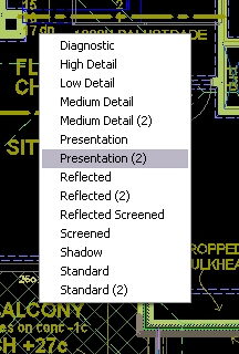
By diving into the DM 'Sets' (see image) and adding a 2nd 'Set', copied of the 1st such as 'Plan', dragging 'Plan' so the mouse shows a '+' symbol and dropping I get a 'Plan (2)' set.  Perfect!  I can do this for however many different display styles I want for the stair utilising the OOTB ones preferably.  So Plan, Plan Presentation,  Reflected, etc.   If you want you can simplify and use the same 'Plan' display for all your different display's whether it be working plan or a reflected ceiling plan.

Now moving down to Representation by Object, scrolling down to 'Stair' and we do the same thing to add another display representation set but this is only going to apply to the stair.  Again this is done to the OOTB template and is quite easy to do, however most times I grab a similar project as a template and it's already set up.  Differently as done for the display representation 'Configuration', I am going to do a little more than just alter the cutplane however don't panic!  It's not complex.   So here we go.  


Selecting an existing display I want to copy for a 2nd floor and dragging down it becomes a new one with a (2) appended.  Ideal!!  Now we just need to scroll across and associate the (2) with the Display 'Set' (2) and unassociate the original with the (2) set.  Ok your way out and then draw a stair in a (Presentation) display.  Editing the style you should only see one set to alter (it's the bolded one). (2) should not be bold.  Now change your display set to a (2) and again edit the stair style.  If you made your changes correctly, you should be now editing a newly created display rep for the stair for the 2nd floor and whatever changes you make will only appear for the 2nd floor.  Now this makes it easy to set up a stair for ground floor showing the stairs going up and for the 2nd floor display with the stair going down!  Or however you like it to show!!  The final display changes can be done in the environment you are familiar with through working the style from the stair itself.  See these 2 images.


Viewports (update) will need to be adjusted for each level displayed. It's seems that if you have not changed a viewports display rep then it will be whatever your current model space is set to.  However if you specifically change the display rep inside a viewport, it will stay that way and not automatically alter (no idea what variable that is).  So if you are setting up a viewport for your 2nd floor, double click inside the viewport and change the setting to Medium Detail(2) or whichever you need. Then also change the Elevation setting and you are done.  If I use a previous job as my template these are already set though the 2nd floor level may be a little differerent height and may need to be altered.  - easy!

Stairs another way (PN & X-ref's).(update)

                                      James doesn't like manipulating layers and would like a 1 file system without having to manipulate layers.  He sent me a file showing a stair that displayed differently in response to it's elevation.  By setting the stair elevation to minus -2900 in the properties pallete, (as you would in an x-ref system for the 2nd floor plan) his stair changed to the 2nd floor display much as I show above but using the same display representation   He achieved this by altering the global  'Display Below Range' to   -2900 (normally set to -300) for that display rep.   Of course this requires the stair set at 2 different positions and doesn't work for a one file system, but may be of interest to those using X-ref's or the PN.  Interesting indeed but I haven't worked out all the ramifications.

Spanning Walls
If you have got a file from me and it has Plan Presentation (2) in the Display Manager under Representation by Object  - Walls, then it's not required except where I was trying for a spanning wall which needed, like the stair, to be able to be viewed differently from the 2nd level.  This would require a style over-ride for a style only used for spanning, or an object override.  I'll have to discuss this in another blog but you don't need this except if you are trying to avoid horizontal lines between same plane upper & lower walls in your elevations. Since I often use alive elevations (the model viewed from different sides with hidden lines) for sketch presentations I've tried to use this option.   I'm not sure it's successful but Watch this space !

Tuesday, January 25, 2011

Mult-Levels in 1 File?

Great to have some interest in this idea.  I've sent out files to some. If you haven't given me your email address I can't email you anything OR reply to you!! As you can see no one's email has been published so be confident I will protect your privacy.  I delete your comment rather than post it.   If you've tried to follow my online notes, it may be difficult and I may have missed things (hopefully not).  It's hard to anticipate everything about someone else's setup. 
 If I send you a file you can compare and see how it actually works (and it does) and, if it suits you, use my file for your template.  Feedback is welcome too.  
My intention is community as I like the open source idea.

This 2nd image is 3 storey for which I had to add another 'level' of commands for.

I'm presently working on a split level house which presents more challenges, some which should be simple to resolve and some are resolved because the typical wall style has it's cut plane over-ridden. I'm adding some extra commands to change the Z plane level without changing the Level you are working on so you can have different levels for the same 'Level'.  A 'Level' would correspond to those collection of levels you want viewed in the same plan view.
If you have specific queries feel free to post a comment but it's best I can send you a file to try it out.  If you are using ACA2011, I am sorry but it has BIG problems that will hopefully be addressed but it does significantly negate partially the reasons for Multi-Level in 1 File (rendering & memory issues).  I may post my totally negative blog review on using ACA2011. For the record my great increase in productivity is in using ACA2009.
And also I say again.  I promote this system for residential and small commercial work. Larger projects should really be done with the project navigator or at least X-ref's but I will be intereted to see how large I can get.  As computers increase in capacity, the size of file you can handle increases.
I keep intending to put some tut's on Youtube on the roof object, rendering and materials and this idea.  Now that I've published it I have to do it hey!  So much simpler to watch instead of just read.

cheers

Saturday, January 8, 2011

Windows & cutplanes

David Koch - The Architects Desktop, has two excellant posts on getting windows above the cutplane to display, something I've always blundered through but his explanations makes it very simple to achieve at least my desired solution .
 
Displaying Windows above cutplane  and
ACA Wall settings at openings. (ok this one is not so simple to understand).

And whilst visiting here, David has a link to ACA / ADT scheduling resources that is very valuable.  He's captured wisdom from some great minds including his own and put them in one place. I can use schedules because of what I learnt from here.

David has help Paul Aubin with his latest update to the 'Mastering  ACA' series of books now called
The Aubin Academy Master Series: AutoCAD Architecture 2011

As Paul tells it, the bulk of the work for ACA has been done by David this time around and my thanks to David for all his efforts on continuing the education for ACA..

I've said before that I learnt how to use the Project Navigator after reading Paul's ADT2004 series and I dived in on a complex project on ADT2005 and was pleasantly surprised how it all came together so well.  Paul himself has some good movies to watch over at Autodesk Exchange, also a great resource.  So recommend Paul's work.

Hope the new year's looking good for you!

Cheers


Wednesday, December 22, 2010

and Now for the Really Important Stuff

Well we're off to a wonderful holiday destination for just a short break.  I think we have the blue trailer and some storage space in the red sea container reserved.  I sure do need the open air exercise and I'm assured the pool is clean.

Thanks for sharing the journey.  I hope you all are holding your own as the world shudders. 


I've been working from home looking after my kids on their aussie break and they have got into Sketchup - release 8 just released.  My middle son has designed his dream house.  Not sure about the engineering issues but it's gets a great view and will catch any breeze!  They have also messed with Envisioneer Express (free).  So if you got young'uns who you'd like to inspire but don't want them messing up your cui or your pallete then these are great simple and free options for play. 

Actually I tried out Sketchup myself to be able to quickly review the sun path for a new display home I'm working on.  It allowed me to quickly test the height and angle of a highlight window design. The sun slider is quick to show real time shadow and I was able to determine refinements required to allow in more winter sun and still block summer sun. I reduced the overhang.   I could also evaluate the effectiveness of solar panel positioning and as here determined that some panels were just not going to be very effective and need another location.

To get your aca model into Sketchup use the 3DSOUT command on a 3d view. (Don't have 3DSOUT??)  You can then import the 3dstudio format file into Sketchup.

I also placed a camera and rendered shots at different times of the day using ACA, easy to adjust the time and rerender but it's not real time.  Just looks better! 
I am working on a 3 level house now and upgraded my lisp tools to work on it within 1 drawing and it's working quite well.  I have another post to share some finer details of my system of working in one file.  I've also added some extra commands that allow more quick efficient manipulation of parts of the building model.

anyway.....

So here's to you and yours.  May you have a most enjoyable Christmas holiday with good family and friends, may your ability to shoulder the troubles increase and your understanding of the deeper things bring you peace.  May your laughter be louder and longer and your tears be shed in joy and in sorrrow with those you love.

In this, His season,
God's best to ya
Cheers from AusACA

Saturday, November 6, 2010

Multiple Levels in a single Drawing File? Part 3

Ok to continue my crazy idea of completing a multi storey building in one file in ACA.
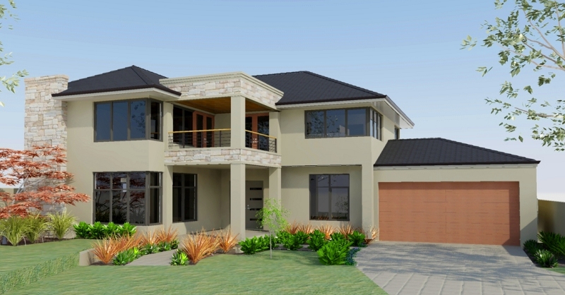
Here's a sample drawing with all layers turned on (not any different to look at from X-ref'd level files) and the rendering (incidently done in a seperate file after the CD's were completed because I couldn't resist.  Design by others.


The Cutplane & Display Configurations
The cutplane determines at what height a horizontal cut is made through your building to show a plan view.  You can adjust the height to cut through the windows or as the default 'Reflected' display rep does, raised it to miss windows & doors altogether. (I lower this to cut frames as I display them in the electrical layouts for residential work).  Now I override the global cutplane for walls and this is discussed here.  This means that whatever height a wall baseline is, it will display normally and not disappear because it's above the Global cutplane.  So this will mean that you will need to rely on other methods to not display some items (walls) that are not in the current level but this is okay because some items ignore the cutplane and don't work like walls anyway.  Here is where I use layers and my first designation in the layer name of it's level (1,2,3, Site etc).  So in issuing a L2 command to flip to the 2nd level I need to adjust the cutplane and I do this by creating another Display Rep.  This is a very simple procedure.  Opening your display manager and noting what Configuration is current (in Bold text). Select and right click and copy and then paste.  This creates the same DR with a (2) attached - sweet just want we want!  Actually that's the long way to do it.  Try Selecting Standard and whilst holding it, drag down and your mouse should display a plus.  Let go and the **(2) file is created.  ('Configurations' are the names that appear in the selection box RHS bottom of your drawing screen).

Now I move to the CutPlane tab and add the lower floor to current floor height to bring the cutplane to the same height for the 2nd floor.  Ok out and test in your display Configuration selection box that you now have a new config to select ready for your second floor. 

You can create these extra configs for any of the DR's that you use.  I would generally only create 3 extra for a 2 storey home and no other fiddling is necessary but you may need more depending on the type of documentation required.


Z Plane and the Elevation
Of course when you draw a wall you need to be able to restrict the baseline to the current level and not snap to some line lower down.  The OsnapZ variable does this for you and the button is to the right of the Elevation setting.  My lisp reads the 2nd floor height you set via a 'SetFL2' command and wrtes it to the Elevation setting and then locks the current Z plane to that height (sets OsnapZ to 1) and you can be confident that the any snapping will ignore the Z height.  Issueing L1 will return back to the ground floor Z plane and elevation height.


Controlling Display
So how do we flip from Ground Floor to Upper Floor to Ground Floor Electrical to roof plan?
Actually I don't use a roof plan but I could.  Simply by using lisp to automatically execute the -Layer command and using wildcards to turn layers off and on I can instantly switch between various groups of layers.  L21 will switch to the 2nd floor but show the underlying walls of Level 1 locked so they can't be moved.  L1E would show the Ground Floor but without text and dimensions and also show the electrical layout not shown for normal Ground Floor plan.   Basically by following conventions and grouping rules with my layer names I can create simple lisp routines to get whatever display I need.  As yet I don't control the Display Configuration via lisp completely and on issuing a level change command, the dropdown list will popup allowing you to cancel (if the current one is acceptable) or select the new display rep to change to.  I know the tools to change are there but I need to step up my lisp learning to get the job done.

So that's it.  Relatively simple for something I desired for years to accomplish and now am using successfully in production with significant productivity increase and ease of use with some simple Autolisp.  As I said at the start, I am disappointed that this wasn't presented as an option now that I know how simple it is to implement.  I am happy to send you a sample file and a copy of my ever evolving lisp file to check out so drop me a comment with you email (will NOT be published) and I can do that.  I hope I have presented this in a way that doesn't scare you off.  Drop back and check out the reasons why this is such a good idea for smaller projects if I haven't yet convinced you.  See here if you missed parts 1 & 2 for all the MultiLevel posts..

Next I need to share just a little more work on stair so you can use a single stair and see it differently on the ground floor plan and the upper floor plan.  Odin Cary discussed this problem years ago here and I did use something of his logic (developed for the PN) to use in my system.


cheers

Saturday, September 18, 2010

Rendering is fun!

This is another project that I keep rendering over again.  I have strict council guidelines to match a pocket of pre-war housing and I have to ensure that I satisfy the gods... er I mean the planners. A pretty picture can go a long way in getting support.  I am not supposed to have a garage door and possibly the brick beam is going to get vetted but I'm hopeful they both have a chance. 


Being able to constantly refine a design, hit render and in around 5-15mins (dependant on settings) I can have a reasonable image to sell the design.  It goes a long way to winning a client.  I will use the actual model, viewed from each side in a viewport with the vp set to hidden for elevations and they aren't perfect but it's quick.  We can use aecElevations down the track when we get serious but time spent rendering will win over everytime.  The included expanded (around 100) RPC's are enough to get you by though you can buy extra as you need it.  To get the RPC's going you will need to download from Archivision.  Look in your browser.  I've mentioned before that if you have a license of 10, you can use the extra RPC's included in 10 in 09 without any problems.

Jay of Visionrez has posted some helpful tips on getting started in rendering in pdf form for you to download.  He explains that it was created for their VR clients but it's mostly useful for anyone using ACA or even Acad.  (Can someone tell me where this is posted?)

Some simple tricks n tools shown in this image.
Rafter ends are a block of the rafter overhang ensconsed in a curtainwall style which automates the repeatable spacing. (I'm still figuring out how to automate the hip rafter).
The front fence is a railing style.
A curtainwall fashioned as vertical blinds create an interesting look behind the windows.
The boarding to upstairs clad walls are a profile applied to a cladding componant.
Roof hips and Gable treatments are profiles (shapes) applied to a structural brace style.
Gutter is a wall style with a profile.  (my typical fascia and eave lining is turned off).
Windows have a surround attached to fatten them up.

Having these items set up ready in a library and in a pallete at your fingertips makes bringing together an image like this an efficient process.

Rendering  .. . .. . you gotta try it.

Sunday, September 12, 2010

Model Rendering (edited at bottom)

James posted some lovely images in the ADesk NG and I thought I'd like to add it to my blog as well as my wallpaper.  This is modeled and rendered inside ACA2009 and shows that it's quite capable of a decent image for presentation.  
One of the tasks for the image is as part of the presentation to the local authority to gain their support for a project that overreaches in some aspects of planning regulations.
A particular nicety in this image is the shade ribbon (a ribbon I like) that meanders around the balconies and brings about a wonderful interplay between the regular rhythm of the balastrade both glass inside the ribbon and solid outside, and the random travel of this shade device.

James has drawn 2 circles, one offset of the other, extruded both and then subtracted the inside from the outer resulting in a tube.  A plan view PLine was also used to map out other flat sections, extruded to a solid, other solids used to subtract portions and after some union'ing the whole lot was converted into Mass Elements. 

I've just derided the overuse of ME's in my last blog but here they are quite useful because as James points out, they obey the cut plane when displaying each floor.  Now He doesn't use the PN but regardless, positioned correctly, the ME ribbons will 'cut' correctly in the plan views whereas using solids would not, having no intelligence of that sort.  Also in this situation the ME 'Ribbon' style can be assigned an aecMaterial and different rendering options can be swapped quickly to explore ideas.  With an ME style, you only need to deal with the aecMaterial and mess with the 'Render' material to do this.  If you used solids here, you would either have to alter the actual render material used (loosing previous options) or create a new material and then remap it to each seperate portion of Ribbon each change.  The style system of ACA works well here although masselements are now more primative than solids and not able to show a true curve being segmented.  But if your settings are high enough (as here) this can be barely noticable.

Oh and James is working on a 64bit system with 8Mb of RAM.  I doubt I could finish such a render on my 32bit home system with only 2Mb of RAM.

tips: remember that ME's can be easily turned into solids and visa versa.  Select the object and RC for options.

I should mention that the first image is an updated rendering. BACKGROUND command will allow you to choose options such as a background image (sky)  seen above, or sun & sky with illumination (no background) seen right.   If you want to place a sky picture in later you can use a solid colour which makes selection easier in a paint program like photoshop or free GIMP.  The Background setting can be saved in a VIEW you create. If you added a camera you will already have a view by the same name as the camera.  Using a camera can allow easier adjustment of the view and easier setup in plan view.  I'm still playing with these settings and cannot get light shadows with a sky background as James managed to get in the top image here so I've gone to pasting skies in later in GIMP.  I'll post some images later to illustrate more on these settings.
James' Tip:  If you are not using sky illumination you may have trouble getting shadows looking anything but dark.  Try GI (Global Illumination) and forcing FG (Final Gather) on (not auto)  (more the FG than the GI).   "It's the only way of achieving lighter shadows if you don't want the generic mental ray background (Sun & Sky setting). I also use the logarithmic exposure control over the automatic."   You can see the Globe button lit up for GI to tell you it's on as the settings display whether it's on or off (no greying out functionality here).  The interface design is rather poor on a number of the palletes in 2009 and I don't think it's really improved in 2011.  Be aware too that these two settings will greatly increase your render times.  For my day to day images I will not use them but if I am trying to render higher resolution and better quality for special shots I will turn them on, set the render to go when I turn the lights out and hopefully in the morning I am greeted with a fabulous image.                                                                                                                          If you are using RPC content then you may be warned to alter your Physical Scale setting.  Be good if the defaults were set already.  James thinks it's 1100.  I thought I read 600.    Oh!   this pallet is raised by the command RPref  .   Sunproperties will open the sun pallete (I've alised it to Sun).
Other settings I know to mess with: If you have lots of RAM, you can try setting your memory limit higher than the default 1048.  With 3.5Gb I have used 1800 but 2000 will crash.  My home system with 2Gb will not get above 1600 (if I am lucky to get that).  If you can get to 64bit and lots more RAM you will have better success trying to render larger images.    At the top you can select from the presets.  Medium will give you a reasonable quick render (5-20mins) but High or presentation turn on FG & GI and alter some of the other settings so only use them when you are ready for the final render.  Of course the render time is greatly effected by what you are rendering, the materials applied, transparency, reflectively and the settings you have applied.  When experimenting don't work on that 18 storey building!  Try something small, even a few masselement boxes on a floor so you can get quick feedback. 

Rendering is fun!!  Go on.  Have a go

Monday, August 2, 2010

Roof Object - Part 12

Why Part 12?  Why not move on?  LOL?

Because I keep finding out things about this RO tool that make it so much more usable and if I knew at least some of this when I was starting I would have been more productive and enjoyed using it more.  So... I want to let you know !!

This one (or two) is fairly simple and is more about technique.  I've now known and used many times (Doug?) my trim trick but I've found out how to make it quicker and easier to use. 

 You ready?? 

Instead of using a line to trim, use a circle.  Pick the corner for your  centre and any diameter will do.  Then issue the TRIM command, pick your circle as a trim object and then your roof eave line and you now have 2 vertices - voila!  (Oh you haven't read my earlier post?)  They didn't tell you you could do this?  

Now it's been great to have someone working with me and my young gun, on teaching him this trick just assumed you could trim an internal corner -- he was successful, but didn't tell me!  He just thought I knew!  Here I am, going to the nearest external corner to drag (stretch) points around into position and all I had to do was trim in the inside turn and I was there.  Sigh.   So simple!

Either way, the beauty of using a circle is that you still have the original corner point preserved in the centre of the circle and using osnaps and the Stretch command you can quickly restore one of the points back to the corner.  I was drawing extra lines before I learnt this trick!

The old idea was that if you had to edit the roof object, you either deleted it and started again or converted it to slabs.  I've learnt so many tricks to this RO that were hidden that it's a long way off from being such a disposable object.  With it's easily edited capability it's a keeper.
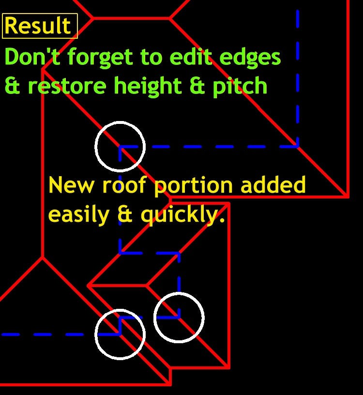
So after editing the edges (see below) we have a new roof.


Here we have an edited roof object, albeit a simple one for demonstration but I hope you can see you've no need to throw out that complex Roof object and start again or convert to slabs just because the client wants to add a sun roof extention.  

I will even edit rather than delete just to see what else I might learn about this creature.

Now remember this tool was created for ADT1 (1999) and it hasn't been improved since.  Wouldn't it be great if Adesk paid some attention to this tool of great promise.

             Some more tips
Make sure when trimming you 'cut' the 'Eave' line not the gutter line.
Sometimes when stretching vertices back in line they may disappear if they have the same height, eave etc.  You may need to re-order your movements to stop them from disappearing or add the eave or difference before moving back in line.
My young partner also showed me how to remove an unwanted vertice - simply select it and drag into another vertices and it is gone.  I've already told you he showed me that Stretching a vertice is often successful where a drag won't budge it .
When you trim the Roof Object, the newly created edges will have their pitch at 90 and their elevation set to 0 and as the 2nd picture attests, that will muck up your roof object shape.  Simply edit the offending edges and set to match your roof numbers and it will pop back to line.
Final tip for now (until another one is discovered).
When you trim a roof with it's elevation not at 0, like my 2nd floor roof within my 'multi-level in one file approach' system upper floor roof, your roof will be set back to 0 elevation.  Once edited, simply retype in the elevation height (2nd floor level) in the properties pallete.

Ok also a BIG apology to anyone who has followed from my much earlier posts on this roof object.  I have mentioned drawing your roof with or setting a slope pitch to 0 when I should have said 90d.  Setting one side to 0 will wipe out any reaction to any other pitch unless that pitching line is above the other so for example when creating a one slope verandah roof you should be using 90 (not 0) and adding the pitch to the sloping portion only.

Saturday, July 17, 2010

Get Rendering

I have a number of posts about my own experiences rendering inside ACA.  I held off using 2007,8 and 9 because I had a quick and efficient system with ADT2006 but I have been enjoying using ACA2009 for almost a year now.  If you are not rendering then you are missing out on the fun.  I thought it would become a slow labourious process with overnight renders and the nightmares to go with it but I've found it almost as quick and efficient as it was in 6 and of course the new Mental Ray rendering engine can produce a higher quality finish.

As a side issue I have discovered that a number of OOTB practises of ACA are detrimental to an efficient process, namely the overuse of MassElements within styles, the overuse and underuse of Render materials and of course the use of the Project Navigator or even X-ref's.  Not that I don't use X-ref's but if you do you have a number of extra steps to go thru to edit files in preparation for rendering.  At best it's clumsy and verbose (but maybe necessary for larger projects) hence my development of multilevels in one file.
So..with the acceptance that I'm no expert renderer and that there are few that are on rendering inside ACA I would like to offer the tips I've learned to get a little something out of this baby.  If you are after the highest quality renders, then Max may be your gig but if you would just like to get a basic good quality render out quickly and efficiently without paying the premium in time and upgrades for another program then you can get there with AutoCAD and ACA.  You also have the advantage of being able to alter the file and re-render without having to learn & link to another separate program.

In ACA assigning materials is a step sideways from the direct approach in Acad which assigns materials directly to an object or bylayer.  With the styles manager and it's matrix it can be a little more complicated.  But that's ok.  Unlike Max which is a dedicated renderer and not much else, you can use the same file for preparing your Development Application and rendering and still rip off quantities so changes need to be only done once.  You could progress the same file to construction drawings and even still use it for rendering at a moments notice!

Here's some links which may be helpful on learning about Acad rendering but also try google.
http://www.dailyautocad.com's%20e-book%20%22creating%20render%20materials%22/
http://alt.dailyautocad.com/files/2009/2009-011-mat-def-toolbar.zip
http://www.dailyautocad.com/2006/01/autocad-tutorial.html#render
Archidigm article on Materials
Archidigm's Development Guide (look up materials (P1) and the appendix at the end for render/materials)

Firstly it's good to get your head around the use of aecMaterial definitions.  That's not just for rendering though they contain the link for any render materials as a part.  aecMats are used to describe how a material when applied to an aecObject will display in any of the display reps (Presentation, Medium Detail, Reflected etc) and in any view (plan, elevation, model etc).  This would generally be understood as a hatch pattern, line thickness and possibly colour shading.  However within this definition set you can also assign a render material (RMAT).  Here I have developed my own thoughts apart from the OOTB system to reduce the number of RMATs used which will quickly bring your system to a crawl, especially if you are still using a 32bit OS.  I also work on more low end stuff and have no time to fiddle and tweak too much so I need a system that will allow rapid development and render.  It's not uncommon for me to start a design in the morning and finish the day with a set of presentation drawings (site,floor plans, elevations) together with a smart render for the cover sheet.  With my multistorey in 1 file approach this has become much easier to achieve.

As for the overuse of MassElements I have discussed that here but in case you didn't get it I'll say it again here.  You don't always need to use a ME for an object (block) that you embed into a style.  I used the example of the aecDoorPanel that's OOTB but here's another example. 

My young partner who is new at ACA created a letterbox MultiViewBlock.  He created a model and 4 views (Plan,Side,Front,Rear).  For the model he used MassElements and for each material created an ME style and then created seperate render materials that were captured in aecMaterial definitions.  Now he did a great job and followed ACA methodology but adding this letterbox into a file added a swag of render materials, aecmaterial and ME style definitions that quite frankly we didn't need.  This letterbox comes in a series of colours but apart from that there are no choices and it's going to look the same in every instance.  So here is what I did to make this object a much more friendly object. 

Editing the 3D model I turned every ME into a 3DSolid using the Right Click option.  I edited the Render Materials so I only had RMats I would typically have in my file (and is on the limited list of materials required).  The cast concrete letterbox can use the same render material that's used for rendered walls (a sand finish render).  The steel letter recepticle can use Paint-SemiGloss though really do you really need to see shine on a letterbox (and add the associated render time).  In the Style manager, using the 'Broom' button sweeps away the no longer required ME styles and aecMaterial styles.  Purging the file removed the unwanted RMats.  I make sure there are no layers in the file and all is on layer 0.  The command "SETNESTEDOBJECTSBYBLOCK" (alias'd by me to FB) rids all layers,colours, plot styles, linetypes, and pen thickness's but leaves the render material assignment assigned.  LAYDEL will remove unwanted layers that won't go.
Now both 'Paint-SemiGloss' and 'Render' do NOT have any colour assigned.  That comes from the object being set to 'ByObject'.  This means that when placed in the drawing I can pick the MVB and without exploding set a colour if need be. (I use aec Standard.stb plot style where colour is meaningless unless told otherwise).  
So now my letterbox can be dropped into my drawing on a layer of my choosing, coloured if required, rendered, all with a light touch and minimum fuss.  Any item that is a specific colour like the backplate is given that colour in the original block (after using FB of course).  You can see you get one selection for colour so it won't work where you need two.

Oh the ME's?  Well if my letterbox was an ME I would have to dive into styles and search thru menu's to find which style was assigned and if ByMaterial, then trace thru the material settings to find the colour.  Now for a wall or roof I use this 'style' process (not always) but for peripheral items (props) like letterboxes it's just so much overkill and takes 10x as long to manipulate.  Dump the ME's and just use plan ol' 3DSolids.

Have you downloaded a block and found lots of weird colours?  I downloaded a speed boat that I've never used.  This one had lots of render materials for seats, chrome, engine parts and nice colours assigned for the paint and the flames.  However the acad model itself was all green!  Now making an entity a colour is simple but years ago we might have followed an office assignment.  Colour 151 = chrome and Colour 204 = red leather etc.  But we don't need to follow such an indirect scheme.  Make the object the desired colour and the chrome silver and then assign RMAT's that have colour ByObject.  I also removed all the layers (no need to assign material ByLayer either).  Now if I ever use that speed boat in an image it won't add any layers, (new) RMATs, plot styles or, linetypes  If I make the body ByBlock I can even colour it when added to the drawing without exploding the block and it has Paint-HighGloss applied so I get a great spray job as well.

It's a prop!  Who wants to spend time fiddling with a boat? You just want to drop it in your drawing and it behaves and stays quiet!  I've used this technique for the car in this image. The car is dropped in (the body is white or whatever the layer 0 colour is) and a colour selected).Now it ain't going to win me any rendering awards but it has won the client over.


If you've had a chance to check out the even newer Mental Ray rendering engine update in 2010 and 11 it may have a high drool factor - the new materials look lovely, but it's going to slow you down and weigh down your system and prevent you from an efficient process.  Check out the paint colours.  Each colour has it's own RMat !! That's a lot of Rmats.  Ditch the colour, make it ByObject and then you can use the same RMat where-ever you use that same gloss level.  And remember unless you are trying to create a high image level, then many of the subtle variations in paint are lost on a simple quick rendering.  Is gloss plastic that much different from Gloss paint.  If you think so then you shouldn't be reading this article.   If you require a specific material like brickwork then yes you will need a RMAT for each different one though for something like concrete pavers you can simply use a bump map and colour ByObject again.

Odin Cary of Archidigm is doing some great investigation articles of ACA2011's new rendering and materials and it seems he's having better luck.  He also has explained the 'jump to perspective' bug that had me in frustration.  Odin has also started renaming the complex and longwinded material names so I am not alone here.

Also be aware I am talking exteriors here.  For interiors the game changes alot.  Rather than the one light source (sun) you need the reflective values of many surfaces to realistically light an interor but to be efficient you can still greatly reduce the number of RMat's used by using the above techniques.

Get in and render!  (or simply!!  then render :-)

Friday, July 9, 2010

Multiple Levels in a single Drawing File? Part 2

Ok so are you interested enough to read further on this idea?
I can promise a productivity boost on residential and small commercial projects.  Following the OOTB processes can at times lead to a lot of the confusion attributed to ACA/ADT when simpler processes could have been put in place.  The OOTB processes are also detrimental to efficient production especially when you want to turn (churn) out fast renders as well.

Here is the recipe on how I achieved it and it was much simpler than I thought it would be. So simple that I ponder why Autodesk hadn't provided this as an option.  Oh and this is just background of how it works.  You don't have to understand or recreate this.

Let's go to the the list of the items I posted in Part 1 in more detail.

A Layer Key Style that holds a Layer designator.
We all work differently and we need to have the items required for our environment. For very large projects, you may have multi disciplinary drawing files but for the most part, I would complete my set of architectural drawings and a structural engineer would complete his own set of drawings. Maybe a hydraulic engineer would be required or perhaps a civil engineer but they would also complete their own set of separate drawings (& CAD files). So there is no need for me to preface a layer with an A.  I preferred the level indicator to be first and I use a simple number. '1'. It's great to open the layer dropdown and type S and go straight to the Site-* layers. But it doesn't really matter because as long as your level indicator is in the same place you can use the '-layer' command to find and manipulate your layers. So 'A-Wall-L1' or 'A-Wall-FLR2' is ok. Because the layer manager dropdown display is so narrow and only shows a limited number of letters I try to keep mine simple. You cannot mix A-Wall-L1 and A-Wall-Blow-L2 though as the level indicator is in 2 different places (3rd and 4th along) (In my system anyway).

(Odin Cary of Archidigm has excellant explanations on all things ADT/ACA in his Development Guide.  Check out under section 2 for Layer Key Styles.)

As an explanation;
From the command line I can issue -layer , select 'OFF' and then using a wildcard such as 1-* have all the layers starting with 1- turning off. (The * being a wildcard for those not familiar). I could also issue *-*-FL1* but of course it will fail if the level is not in a consistent position in your layer names. If the level is always in the 3rd position it should work. Therefore I chose to put it in the first position and also allow me to sort my layers naturally by level.
(I've seen a wish list item posted several times to allow layer groupings, but this is not available at this time).

However this does not prevent me from sorting via major item either. Issuing the -layer command again and OFF and *-Wall* would turn all wall layers off regardless of their level.
So from this basis we can turn all layers off using the * wildcard and then turn back on those we want to work with. Therefore in lisp fashion the following lines...

(command "-LAYER" "m" "0" "F" "1-Elec*" "OFF" "*" "N" "ON" "1-*,1+*" "")


...sets layer 0 as the current layer, freezes the electrical layer (as I only want that one on when doing electrical layouts), turns all else off, then turns on the level 1 (and 1+) levels (except the frozen electrical layer).

My system uses the difference between freeze and off for layers. Frozen layers do not regenerate and reduce the load on the display system. Off layers are generated though not displayed and are quickly turned off & on. So by freezing layers I don't want to see for a while and turning off layers I might want to edit quickly in my next move, I can have a fast responsive system.

I used the 1+ Stair for items that would span more than one level so they would show also on the 2nd floor as well (but with a different cut plane and display rep - more on that one later).

So if we tie the above lisp line to a simple command, say 'L1', then we have created a new command to show us all the layers on level 1 only. More on this layer..er...later.

I also use other 'level' indicators to sort layers such as Site-, 3D- for info only used for modelling or elevations and not required in plan views. Your Layer Key Standard will set whether your layer names have to follow a strict or loose convention. Some LKS's have strict 1--4-4-4 numbers of alphanumerics generally with the last 2 places being optional. Mine has no restriction on the number of each. I find the AIA layering system, designed to organise a hospital complex way overkill for simple residential so don't feel tied to such a system if it's not needed. 

Hey try this. If you have an x-ref in your drawing, use the layer command to freeze all it's layers like this -layer F X-RefName|* The | symbol is shown in the layer name itself in the Layer Manager between the x-ref name and the layer name (inside the x-ref).   I have my survey as an x-ref named 'Survey' and using this info I can freeze all survey info in my drawing using lisp.

All new to you? Open your Layer Manager and click on the 4 buttons top right. I'll try to add some good links here for simple tutorials on these great and powerful tools.

Can you see why I have dropped the A- from my layer names. Layers are sorted alphabetically (of course) and you can use this fact to your advantage in your layer scheme. Even keeping your A-, what comes after will determine the sorting order.  In the layer box you can type say 2 and it will scroll to all my 2nd floor layers.

Place to hold your elevation floor level heights.
If you want to switch to the 2nd floor, you need to be able to draw a wall at the 2nd floor height. This height needs to be entered and available to the drawing. I did want to use Fields but as yet I don't know of a way to access them in lisp (strange!). It needs to be saved with the drawing but it's not a drawn entity.  So for the moment I have elected to use Autocad variables (thanks David Koch)  Acad has 10 user set variables available that are stored in the drawing when closed that I can enter and access.  I chose the interger based as I work in mm and won't be requiring any decimal places. If you have decimal places in your floor heights, you will need to use the USERR1-5 system variables as the R stands for REAL.  I assume level 1 at z=0 but level 2 is set in 'USERI2" and level 3 in "USERI3" etc (the 'I' here is an i). My loaded custom autolisp file reads this variable when I open the drawing and assigns the variables FL2 and FL3. These variables (FL2/3) will be lost once the drawing is closed hence the use of the system variables to hold the values over.  An easy way to access these is thru the 'System Variable Editor" available under the 'Express Tools' under 'Tools'.

Now don't worry if this is all confusing to you. I am just trying to give some background info on my method of madness. I can send a template or sample file to you that has these items set up already and I have followed OOTB methodology as much as possible so that I have minimised my customisation. My overriding rule is to Keep It Simple so I assure you it's not complicated.

Next .... Cutplanes, Zplanes and switching Display Representations.

Tuesday, July 6, 2010

Free ADT teaching vid's and other news.

Daryl Gregoire of CadClips has just released his ADT and Autocad video's for free viewing.  Looks like he stopped teaching at version 2008. Not too much has changed since then anyway.   I have had CadClips link on my page for some time so you may have already visited but if not pop over and you can get an online video review of that difficult to grasp concept. 

Perhaps watching someone do it will be the thing that gets it to sink in!  Watch them here

(pssst  you will even see some Revit video's too but you won't here it from me!

Matt Stachoni is a heavy weight in the installation and setup of AutoCAD Architecture and it you have some questions on how to install and where, his guide, available at his new web site aecblog will make a good night time read.  (At the time of posting this it was off-line but come back to it).  I only do single installations so all the network stuff was more than I needed but I enjoyed his hints at how to hack the dialogue boxes.  You know when you have to keep enlarging them EVERYtime and it gets old.

and in some interesting news Dell Not so Swell

Is there any company that's reliable and trustworthy to deliver and full working product anymore?

cheers