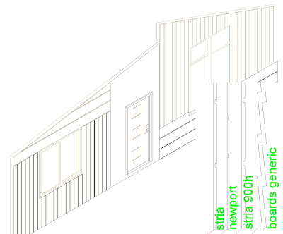
I'm sure you are familiar with profiles in ACA. The rendered project I posted below will be cladded with JH products Primeline Newport and the new Scyon Axon and an even newer product called Stria.

I tried to use bump mapping to produce the boards in the render as I was trying to keep things simple but it just didn't work well. (Rendering in ADT6 – maybe it works better in Mental Ray of 08/09). So I returned to adding profiles to the boards but how do you do that vertically for the Axon? ( BTW MEP has tools to do vertical profiling. Not sure why we don't need them in the Architectural package.) But first, in case you haven't used profiles in a wall style here are the steps. It's easy & fun and gives great results.
Before applying a profile, I need to prepare the wall style with a cladding componant that is going to have a profile applied to it. As I am keeping things simple I do not have an interior plasterboard componant but I will have a 20mm (nom) external 'Cladding' componant defined with an offset of -20 to sit outside the setout line (as the setout line is on the wall timber or steel framing not to the cladding as is standard practise here. Some points to consider ;
- The componant width is not critical as it will be replaced by the profile. In my case the offset needs to match the width so the profile lines against the outside of the framing.
- To create a profile, create a closed pline in the shape of the cladding. Select the PLINE and right click, Convert to – Profile. (Another great addition to ACA thanks team).
- The profile will have an insert defined and this point will coincide with the base point of the componant. I've drawn a (faint) red line to show the insert points to the profiles in the illustration. I didn't find it easy at first but now that I know what it will do it works quite well. So if your componant starts 900 AFL then that's where it will apply the insert point of the profile. BUT it will not stop the top short of the wall height even if the componant it replaces does. It will project to the top of wall (even if angled).
- You need your profile to be higher than the highest point ie. Any gable etc where you want the profile to apply. The profile will be trimmed to the wall height. If you project your wall to a roof, it will correctly trim the profile as shown below as long as you tick the box.
- You may want to exaggerate your profile a little for rendering. I have deepened the 'grooves' in this example and the shadow lines are still quite sutble.
- Your profile can also be used for sections to illustrate cladding.
- When you create your aecElevations, your profile will create object lines as ACA will trace the actual profile. This can be heavy at smaller scales so you may want to consider options. 1. Happily change the cladding lines to a lighter componant in your aecELEVation style using the Edit Linework option or 2. Add another componant to use when creating your aecELEVations that only has a hatch applied and turn off the profiled componant. ie. You could have the profiled componant turned on in your Presentation / High Detail display rep and your hatched componant turned on in your Medium Display DR to use for creation of your elevations.

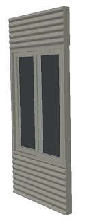
 wall panel from a file supplied by Dermot. This will give you a small mess in your elevations which may not be helpful but it really does make a big difference if you render and also looks great on your aecSections. To get around the elevation mess, try adding another duplicate componant in your wall style and apply a hatched aecMaterial. Depending on which view you are after, you can turn one or the other componants on/off. Takes a little setting up but then you can use it again next time.
Tip: set up an Alias of IP for inserting a profile as a PLINE in your drawing. The full command is AecProfileAsPolyline. I find many times I have to insert the PLINE back into the drawing to adjust something and redefine as a profile to get things working as I want. You can also use an existing profile to make a similar new one. When you insert it into the drawing, insert at the end of a line so that you know where the insert point is.
Next up: Vertical profiles (without using MEP)
No comments:
Post a Comment