Monday, March 15, 2010

Roof Object part 10 - the Hole Truth

Ok I did say I would offer another tip about putting holes in the ACA Roof Object.
Well the Truth is you can't.  Be nice to be able to wouldn't it!


UPDATE: Best practise shown in my video on youtube here.
Whole Roof Object Playlist here.

But I can get you close enough to get the job done in an efficient manner without resorting to slabs.

Here I'm going to show you how to create....

Dormer Roofs (ok this is another Sergej tip and he keeps telling me I have to share this one) but this technique could be used for adding any hole.

We start with our roof sketched out using the roof object.  We add our dormers, and it looks great on the sketch & 3D but now we are onto working drawings and we want to subtract the holes to do sections and interior shots.  Ulp!  Do we explode to aecSlabs                                            NOooooooooooo!

Here's what I would do : 


Note 1;  Odin has pointed out to me that you don't need to start with an ME.  Using the command MassElementConvert (or just type MassElement and use the C option) you can turn a roof odject and many other objects into an ME.  I tried it with a mess of aec objects and solids and it worked with them all.  If you have shapes that are part of your roof that are not suited to a RO or even slab, then feel free to use any object required.  He also emphasises that using the model explorer will allow you to edit more freely later whereas my approach means to edit is to basically delete or keep the original elements to remake your shape. You then have to freeze or export the objects for safekeeping but  the brilliance of the MODELEXPLORER is it keeps all the objects hidden away unless you need to access them.


OLD SCHOOL NOTICE:  Subsequent to Odin's helpful tip this is not the preferred method although it will work.  The Best approach (See Odin's note) is to use MODELEXPLORER as it retains all the parts of your roof and you can edit later.


Create a small MassElement (ME) (*see note 1 below) on your roof layer in one corner in a style defined as 'Roof'.  This should be completely inside the roof object (It's going to disappear).  Next we create ME objects to use as subtractives for the dormer holes that would be cut out of the main roof.  These have no need of any style.  (*1 After we've finished maybe put these items with your main roof object onto a non-print layer to be frozen later or WBLOCK them out as a separate drawing (out the way) as you may want to go back and edit the roof.) 

Select your 1st ME, right click and add (union) the roof object to the ME using the Boolean functions and then also Subtract the dormer hole objects the same way.   No need to add the dormer roofs as they can stay separate roof objects (unless you want to!).  Done!  You can add the roof material to your roof ME style the same as the RO's.

*1 Keeping the original roof object and negatives allows you to make adustments later if required.  Reposition and recut holes.

You know this is a great trick and the funny thing is that Odin Cary showed us all years ago in this page in his instruction set.   I did read it but didn't understand the potential.  This method improved and simplified in the next release after he wrote his article and I show here how simple it has become.
I've shown a simpler example so hopefully together we can show you that this could be a great option to create that Dormer roof or other complex roof with a hole for your next project.   Odin's example uses the model explorer which still works and may be easier to edit but it's no longer necessary.  


Tip:  When creating the dormer roofs here I made a square roof and gave the back edge a 145d pitch (180d - 35d (my roof pitch) to get the dormer to run into the roof.  However the Roof Object will give you am unwanted face on the inside and also square off the overhang where it meets the roof and I had tricks to work around this - WRONG WAY.  Duh!  Create a 5 sided object with the back 2 edges at 90d to nestle into the roof.  Simple & done.

And that's the hole truth.

.
Cheers

Tuesday, March 2, 2010

While we are on the subject of Roof's


Just to be sure that you know that both Sergej and I are crazy about roof's, here are some interesting buildings with ...well interesting roof's that can't be done with Roof Slabs or the roof object.  Maybe with the new Mesh tools in v2010.


A side bar link has some interesting buildings as well.

Cheers 

Sunday, February 14, 2010

Plane Cutting Remarks

I did a project where I placed many simple house models on a hillside for a design scheme and development approval. However it was ridiculous that I couldn't show the houses at their correct elevation and also have a plan view showing the internal layouts (walls) because the global cutplane was either above or below many of the houses. Dermot posted a NG question and in conversing with him he provided me with the answer to this dilemma. I was very excited because I had even had a response from one of the ACA team who said it couldn't be done. I'm sure I was misunderstood because this situation would occur on many campus, hospital or school projects but I was told it was not a common situation and wouldn't be addressed. I wanted an option to be able to override the Global Cut Plane with the x-ref's CP which would assume the walls are sitting at 0 and would cut correctly for plan view. (I was using the PN).

However, the solution was much simpler, thanks Dermot.

I simply overrode the Standard Wall Style cut plane (I have no style overrides to my various wall styles because they are set up to display ByMaterial and follow the std wall style).

(Any specialist styles like cabinets, eave, kerbing, built with a wall style already have their own CP override in the style.)

The effect of this surprised me! With a wall style using the Global Cut Plane, when you raise the wall it will disappear when it is no longer 'cut'. However, override the wall style CP and you can raise or lower a wall as you like and the wall will display perfectly. (It will cut each wall based on the it's cut plane and THAT wall's baseline). I was very surprised and excited that it was so simple. Whilst it obviously overrides the cutplane, it's not obvious that it also overrides the baseline that the CP height is taken from. So why doesn't the OOTB standard style have it's own cutplane. I can't see any advantage to use the global cutplane. If you work with straight single or 2 storey construction this problem won't be obvious to you but as soon as you do a split level it becomes a problem to get a mezzanine to display correctly. With the new cleanup rules introduced in v2009 it's easy to create the 2 floors at their own 0 and still have the walls cleanup.


So now I can have units at varying heights and each one will assume it's own cutplane at the right height according to it's own floor level. This behaviour will occur whether I am using the PN and /or x-ref's or it's in the same file. I've been wanting to work with multi storey in a one file approach for years and this tip was a key to allowing me to make this happen easily - thanks again Dermot.

Thought!
It used to be hard to get a high window to display. You had to override the style display rep to raise the cutplane. Unfortunately overriding a cutplane will require to cut that wall (style) off from it's parent wall style and it will no longer respond to style adjustments made to the parent. In ACA2009+ you can have the baseline at various heights and it will still clean up so maybe instead of overriding the cutplane, it might be an option to raise/lower the baseline and adjust the bottom and top of the wall instead (as long as you have this blog tip in place!).

Wednesday, February 3, 2010

ADT on the Roof

ADT on the Roof

I just had to post this one. No idea of the story but thanks for sending it in Sergej.

For those new to the game, ADT (Architectural DeskTop) is the old name of Autocad Architecture from version 2008 and prior and Sergej is enjoying a joke at our shared obsession with the ACA/ADT roof object. Him as the creator and myself as an avid user.

Even my wife thought it was funny!

Cheers

Friday, January 15, 2010

Roof Object part 9

(Yeh I know, like a dog at a bone....)

I just had to post this little gem from Sergej. He emailed this cute cottage pic showing a portion of roof that neatly meets into the main roof without influencing it.  Notice how the entrance roof joins into the roof on the left but there is a portion of the main roof behind that continues as though this lower roof is not there.

This doesn't work with the ACA Roof object  I had no ideas about how to get this to work except using a separate object and trimming them around each other. Trouble is how to work out where to trim and how to keep the slopes correctly orientated.
How about this! In Sergej's Spirit roof object using his 'sub-roof' , Sergej can get the minor roof to nestle in there like a suckling lamb and muma bear is just as sweet as. (Sorry about mixed metaphors an' all). This is all done with a few minor clicks and is a simple affair. Here's a pic of the Spirit Roof shown against the ACA Roof Object's effort.

Autodesk please let him have another go at the roof object.  With all the time he has spent honing his roof programming skills he could give some great upgrades to this roof object tool.

Here is another not uncommon situation where Sergej's updates to the Spirit tool would be great if they were available in the ACA Roof Tool.  Here I show an octagon roof that nestles at the corner of a hip roof. Using the RO, we have no way of adding the extra slopes because they are inside the controlling edges.
UPDATE: See youtube video where I describe how this CAN be done using Odin's MODELEXPLORER trick
Here is a coloured view showing showing the Spirit roof with a Sub-Roof object.  I've yellowed a portion of roof that has no controlling lower edge that's perpendicular to the slope as you require in ACA (including the aecSlab Object).  I could see that I could use a second roof and trim it to shape but the slope is hard coded to be perpendicular to your edge so it's going to fall apart!


I might come back and have a look at how to work out the trim lines on the 1st roof I've shown here but as a hint, it involves constructing the 2 roof's ensuring they are interlocked and taking a snapshot in plan view (hidden line) to get the right roof lines and using those as trim lines. The connecting roof' edges will have 90d slopes.  We could do the same for the 2nd example I show here if I leave tiny 90d to slope control edges and hope no one notices.

Sergej tells me that with his Spirit sub-roof, he can create the 2nd roof and have it automatically calculate how it interacts with the main roof, subtract the overlapping portion and still maintain all it's slopes.  What's more it can be amended and still update correctly.  I assume it remembers the original trimmed perimeters.  Oh to have that in ACA!!  Yes please!   UPDATE: It was thinking about Sergej's explanation of his sub-roof mechanism in his Spirit roof tool that brought me to the understanding of how we can do it in ACA. It's the same way just not automatic like his Spirit tool. I'm sure you could resolve the first example I've shown here as well using this method. 


Another problem solved with the ACA / ADT roof object !!!!!!!!!!

Tuesday, January 5, 2010

Roof Object - Part 8 - getting round it!

continuing my rants on the ADT/ACA Roof Object (not slabs)... (see all roof object posts)

Creating a Round roof
I'm sure you know that you can create a round roof, either as a complete circle or as part of an overall roof. When you select a round roof, each arc will be an edge with 2 end points and a mid point even though you may appear to have many hips. You can change the appearance for the smoothness of the curve (& number of hips) by editing the edge (Selecting the Right Roof Object and Right Click option) and increasing or reducing the number of segments (max 30) to represent the curve. Whilst 30 may look the smoothest in real terms, a round roof is built with a number of segments (hips) so you may be best to match the contruction number for an accurate representation.


There doesn't appear to be any way to create a curved roof using the command line but you can create one by applying the Roof tool to curved linework or walls. Note that ;
  • You cannot create a completely round roof from a circle linework or 2 Arcs so use 2 arc'd wall objects (2 arcs - because you can't create a completely circular wall with one wall either!).
  • You possibly can't create a roof with a round portion from linework unless it's a closed polyline. (Well that's how I had to do it).
Curved roofs

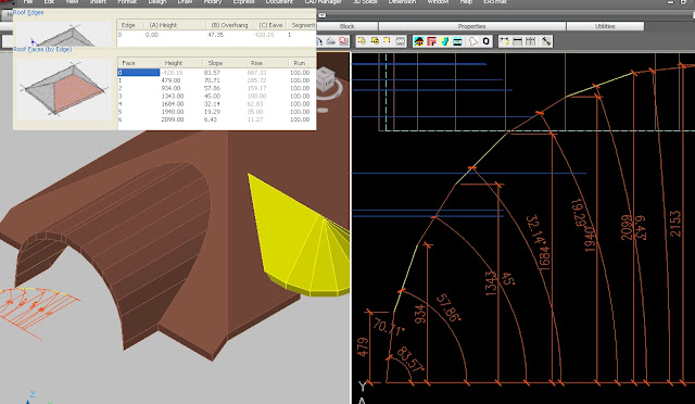
You can also create curved roofs in the vertical plane for barrel vaults, eyebrows and igloos. You can't create a smooth curve but can add multiple changes in pitch to approximate the curve which again is how they are generally constructed in real life. Now the effort to add these multiple pitch changes is no small task so you would like to know how the resultant estimate 'curve' will look before you begin to ensure you are going to be happy with it. Also you need to be able to enter exactly each pitch and height changes to get the appearance of a constant curve not spend all day guessing at the numbers? So how?

Well I have a simple idea to give you the exact data to be entered in the roof edge to get exactly the result you were expecting.

Draw your Arc in elevation view as it would appear adjacent with the model. Use the DIVIDE command to place Points around the Arc. Use an even number to land one point at the apex if you drew the whole Arc (I only drew half!). . Draw a PolyLine on a different layer joining the Points and then turn the other layers off. You should now be left with the Polyline stepping around your curve and be able to estimate whether you are happy with the resulting estimation of the curve. (This will be on your aecElevations as well as any rendered model.) If not - erase the points and use the divide command again increasing the points if you want a smoother curve. Once satisfied, you can dimension each point by angle and height as shown above and this will give you the numbers you enter into an edge on your roof object. OR... you could simply draw a polygon instead of the PLine and have your segments a lot quicker! Again adjust the number of sides until you are happy and then use the procedure above to measure each point to enter into your RO. He's pointed out this is also useful for Roman & Gothic arches. Thanks for sharing this cool tip Robert. As James points out, you can also attach an edge profile to an aecSlab to create the curve. Your slab would be a very narrow ridge at the apex and the curved profile both sides would give you your round roof. You can trim slabs with a pline to fit it into your main roof.

TIP: Be aware the height numbers are for a roof object with it's elevation at 0. If you need to adjust for a different baseline of your roof object, stretch all your dimensions (not the angle ones) down or up at once if necessary to add/delete any extra required.

With this technique, you can create an Eyebrow roof out of a normal gable roof as illustrated, or a barrel vault roof or your own special creation etc.

There is a limitation of the roof object shown here for the eyebrow roof. The Roof object thickness stays perpendicular to the main roof pitch and does not dynamically adjust with the changes in pitch as shown in the picture. For me this would be covered by a gable end treatment (Structural object) but would also be evident in any section. (Note that Sergej's updated Spirit roof tool has no problem with keeping the roof thickness constant!)

Inverted roof
You can also create a Concave or Convex (bullnose) curve to your roof though I may use a wall style for these (see here and here). The other option as James has shared is to add a profile to a slab object so the slab itself is only a very small postion and the curve is achieved with the profile. Very easy to do if your roof line is constant.


Copy & paste Trick (sergej's tip)
If you are looking at doing multiple pitches to more than one edge with the ACA Roof Object as shown above, it can get tedious real quick entering each height and pitch on a number of edges. However once you have entered a series to one edge, if you click in the first column of the face box and Control C to copy, you can then move to another edge and paste the same numbers (yes all three columns). If you had originally selected the 2nd (or more) edge already, it will be available in the dialogue box to paste to. Ok it's not perfect. Be nice to be able to alter a number of edges at once but it's quicker than doing each edge individually. Oh and it is a little temperamental sometimes and may need caressing to get the paste to overwrite.

Oh didjaknow?
  • When you create a roof object, it remembers the last pitch for next time but not the last edge cut. (I think it writes it to the registry!)
  • Once you edit some of the edges, adding gables etc, you may not be able to edit the main pitch via the properties pallete and may need to edit each edge at a time! Sigh! Therefore it may be quicker to remove a pitch (gable?) adjustment, change the roof pitch and then re-enter the gable.
Cheers!

Monday, December 21, 2009

Welcome to new bloggers Doug Bowers & Anthony Mason

Doug Bowers has joined the blogger ranks and has some great tips to share for ACA along with Revit. Doug has taught at AU and is on some of the teaching vid's or articles I have downloaded over the years so you can be sure that he has and will have some worthwhile posts.

I have added his site to the links on the left.

Also Anthony Mason has just started a blog on "....CAD / BIM / Procedure / Support Application / AEC...". Anthony is a long time ADT/ACA user and now CAD manager (or is that now BIM manager?) and an active contributor on the newsgroups. He's just about to start a project in Revit Arch. so I am sure that will occupy his mind but hopefully he will still have some good tips to post for ACA.

Thursday, December 10, 2009

Rendering in ACA


James recently posted an image with a query but he really should have been posting in the gallery section. These images are lovely so I asked him if I could post here and he sent me some different shots. James has developed the 'white' method of rendering without materials which really allow you to review the building form without the complication of considering colours and materials. If you are wanting to get into rendering, this might be a great way to try. See my original post on James' method here. Also my method of achieving this scheme in the OOTB display reps. Sweet James! Thanks for sharing.

Monday, November 30, 2009

AutoCAD Mechanical vs Mechanical Desktop

Earlier I wrote about the demise of MDT and yet saw it still advertised on Adesk's website.  However I now understand my confusion.  There are two products here.  MDT was a 3D product that made it to the 2009 versions but is now no longer available.  For a while it was only packaged with Inventor so that users could move across gradually.  AutoCAD mechanical is a 2D and probably uses contraints and dynamic blocks etc to assemble drawings.  An explanation is on this NG entry. and news here.

Sorry for any confusion.  I thought MDT became AM just like ADT become ACA.

So bottom line is that MDT is now gone - but it did take a while longer than Adesk anticipated (at least publicly).   It's already financially attractive to move over to Revit from ACA and I expect as time goes on that they will make it even more attractive to move over so if you are happy with ACA then stick around.  There will be better offers on the table.

Bottom line for me is that ACA is performing well in our office.  The newbie is catching on to ACA well (admittedly he's not your normal 'which Icon do I press' kind a guy and is happy for me to customise him) and we won't be moving any time soon (if at all).  My multi level in one file approach works well (heck even Dragonfly can do it!) and the process and system is streamlined.  A salesman (ex designer) is trying to get me to move to ArchiCAD which is big here but I want to earn not learn.  I've spent long hours learning 'how' in ACA and now am enjoying the productivity of knowing a product well.  Why would I want to start all over again? (Well for one ArchiCAD's Building Model Explorer is an awsome tool and cane's the pathetic Design Review or Navisworks into the dust for touring a building).  But that aside I'm sticking with ACA.


Wednesday, November 25, 2009

AutoCAD Architecture 2010 Subscription Advantage Pack - Renovation Extension 2010

If you missed it in the side bar the ACA team have released an extension for those doing renovations.


I know this has often been a request item in the newsgroups so I'm sure it will be welcomed. Follow the link above to read the announcement on the Between the Walls blog or head over to the subscription centre for the download.

I have reviewed a 3d picture created with this pack apparently so there are other bonus's that aren't mentioned in the promo. Paul Cloutier has been doing renderings inside AutoCAD (not ACA) for some time and shared this image. Hopefully the ability to do this is also inside the ACA pack - I would have to assume so. Once loaded, you can use the mouse to rotate your camera view to look all around.

Odin Cary of Archidigm.com has done an in depth review of the extension.

Saturday, November 14, 2009

Roof Object part 7

Ok I'm still playing with this tool and have found good solutions to some other difficult roof layout problems. (ok I also got some inside tips from the creator).

(Click here for all Roof Object related posts)

Rising (Falling) Eave (Sergej's tip)
Think of a barn roof with an angle sliced off and you still want the roof to look as though it's on a square footprint. You don't want the odd angled wall to affect the ridge line and it's not obvious how! Here's a very simple work around. Have a very small straight edge before the raking eave! You can make the straight edge so small it won't appear even if dimensioned but it will still get you the effect of what you want if it has the roof pitch. In fact you can use the trim command on a squared off roof which will automatically set the angled edge to 90 and it will work (Just make sure to leave a tiny portion straight. How easy was that !!! Slabs peh!

Constant Ridge Line
This is one that I have recently discovered because Sergej asked me how long it would take to do this with the ACA roof object. He can do it very quickly in his Spirit's roof tool. First let's look at a simple example. By setting the recessed edge to a 90d slope it no longer influences the ridge line and we get our straight ridge.

But if we have another edge it no longer works so what can we do. You may have tried to guess a height and been frustrated that you just can't quite get the exact height required to heal the ridge line and an undesired line appears in your plan view.

Well here's another use for my Trim trick. Draw a line across in plan view from your inset roof position and using your snaps draw a diagonal line from where it intersects your main roof and trim the roof. In isometric view you can now use the ID command to get the exact height at this point. NOTE: YOU MUST HAVE UNITS SET TO MAXIMUM accuracy to get this to work.

Copy the z number from the command line to your clipboard using Control C. Now undo (control Z) the unwanted trim restoring your roof and then select the difficult edge. Pasting your z height into the edge height and restoring the pitch if necessary and your ridge line will be whole again. Wow! That was easy too! Too Easy! And you thought slabs were necessary!
(Tip: If your roof object elevation is other than 0, you may need to add that to the z number to get it's height correct)


Here's ACA roof objects (3) of the original roof picture that Sergej sent me thinking it would take a long time to produce with his ADT1 roof object but it's cleverer that he thought! Using the above trick for the difficult 2nd edge on the same slope and the trim command I had completed it within minutes of him sending the photo.

Hole in One
No not golf! When people ask how to create a hole they may be asking several things. Here's some tips for creating holes in different circumstances.
Dormer Holes
I will deal with this one in a separate post but there is a solution using the roof object that may suit your situation.

Wrap around verandah.
Let's say you have a colonial house with a verandah all around. Is there a roof object solution? Well I've surprised Sergej with this one and he calls it a bug but it does work. Add a 2nd pitch to just one edge at 0d and the centre disappears. Ok you will need to experiment to get the right height (maybe use the trim and ID command??)
Try it with a round roof!


Also try a double slope roof and set the 2nd slope to 90d. (This is Sergej's official solution!). mmm.... that might be a simpler solution!

Central Courtyard
How about a central open hole as in a chinese courtyard. I haven't found a way yet but you can wrap your roof mostly around the yard and finish each end very close together to give the appearance of there being a hole in the centre. The point about doing it on a corner is there is already a line there and an extra line slightly apart will be invisible.

Well hopefully again I have challenged your view of the limitations of the ACA/ADT roof object. Yes it does have them but they are probably a lot further down the track than you have been given to believe.

Why would use the roof object over slabs? Well it heals itself as you stretch prod & alter the shape. That's got to be a good idea. In my work on putting units on tight sites I am constantly stretching and moving portions around and to have the roof just 'deal with it' is great. I hope to post some competent solutions to dressing off your roof both for rendering and elevations in the future as well as just maybe some more tips so come back.

Monday, November 9, 2009

Up on the Roof.

I have to tell you a story about the ACA Roof Object (RO). When I discovered that you could trim it and get another vertices, I emailed (first time) the ADT master, Cary Odin of Archidigm and asked him if he knew it could be done. He said he had trimmed it straight and the result wasn't too productive and thought no more of it. He also mentioned that he had spoken with the german programmer who created the roof object, having once worked across the road from Autodesk and being able to converse with some of the programming team in the early days.

Well that spiked my interest because now the RO had a human behind it and like others in newsgroups, I have complained about it's limitations and lack of improvement. I wondered whether he minded the negative feedback it received which was really the fault of it's development being abandoned though thankfully it's still intact and working in the current release. Cary had mentioned that the programmer had said it was created to do a lot more than what we see.

So on top of my blogs revealing what the RO can do, I 'hatched a plot' to make a very public statement about it's virtues, sharing tips and tricks and showing how useful it can be and also to help understand it's rules and limitations. I made a public loud noise to see if the original programmer would reveal himself. So I posted my Hints & Tricks .dwg file in the Adesk NG and at AUGI. I was already happy to share my tricks but I also thought it would be interesting to see if he could share any hidden tricks that we hadn't discovered and also maybe what he thought of the whole 'roof object' discussion. Maybe I could convince him to create his own advanced roof tool plug-in!
Well I was surprised when I got a curious message on AUGI from a 'german programmer'. Emails went back & forth and now I know that Sergej Alexandrow, (a Russian immigrant) returned to Germany after working with Softdesk and then Autodesk on ADT1 in the U.S. and went on to create a new roof tool for a German CAD company Softtech (English version) within the program Spirit . Dr Sergej is a professor of mathematics (figures!) and has worked as a programmer, mostly on 'roof's which is his first love. (Here's one of his Spirit roof's)

So I now have a few more tricks to share with you from the creator himself. I've even been able to share a trick or two with Sergej although he calls one (at least) a bug, but it's a useful one just the same.

Sergej has reminisced with me about the old days that he shared with the other programmers, some with whom he still works with today on Spirit. Sergej has now started a blog with some samples of his Spirit roof tool in action and yes some of them are just plain wacky (or scary) but he shows a number of tricks that we ACA users would love to see. Curved (both planes) roofs at a click, sub roofs, roofs with holes and dormers! Roof overhanging roof! Multiple slope roofs!, Hands up if you would like to see that in ACA?

So what of the ACA roof object? Sergej has shared with me what he is able to do in Spirit's version and how easy it would be to update the ADT1 version of the roof object to do so much more. But Autodesk has not the desire (yet?). Why? Why are they (intentionally?) crippling this great product with a 10 year old roof tool that they refuse to update despite many calls in the wish lists. I've seen that Revit now has a complete roof package tool. Why not ACA? Is there a political agenda rather than a customer based one? Is it because they want to force you to move to the more expensive Revit package? What other explanation am I left with?

It's time again to review what's possible and easily accomplished by Autodesk in ACA and make some more noise so they know we haven't forgotten about the roof object (as though we accept the cludgey roof slabs as a peace offering). We want an improved roof tool. Even Roof slabs are not that clever anymore and badly in need of much more of an overhaul than they got in 09 (*1).

Stay tuned for Sergej's tips on the roof object - the ones I missed.

(*1) (slice a smidgeon off the Ribbon budget).