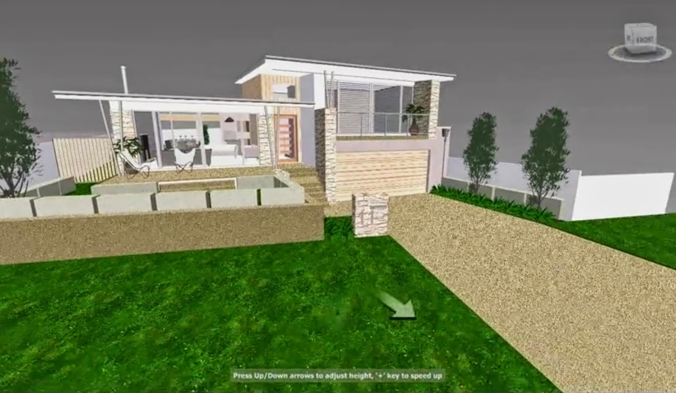
Here's an impressive presentation for Vectorworks 2015 showing some great features. Some like Curtain Walls ACA has had for years but others like walk-throughs look much more impressive. It's named 2015 because it's being released just prior to the year 2015 unlike Autodesk which pretends to release next years software a year earlier and instead gives you software at least 5 years behind, some parts are back in the 90's.
Interesting that at 23 seconds in it shows you an intelligent graphic way of using the numbered keypad to quickly select views and animates the changes in view on screen called transition animation. I showed how to use lisp to do this when I started this blog.
See it again here under the sub heading View Direction. (I could never figure a way to graphically illustrate this cool tip). Of course we now have the view cube in ACA but I still use the numeric keypad, just like I mostly ignore the ribbon.
ACA has had it's strengths and still competes well but without continued improvement especially in the weak spots like walkthroughs but without continued real improvement it's just getting old. I for one doubt I will ever trust Autodesk again with my time. Personally I am much done with learning something unless it's going to be productive (make me money!) and I have spent considerable time on each upgrade not spending time learning great new tools and tricks (because there are none) but trying to learn workarounds for new major bugs that have been introduced. It's sad when the biggest items introduced into new releases are faults in the software!
Here's a screen grab from my walkthrough using Autodesk Designreview tool. I can simply export it from ACA as a .dwf, open in Designreview and take a rehearsed walkthrough and capture the screen as a movie, post on youtube for clients to review. Problem is, half the time the export fails for no given reason and the result quality is about level with the games I was playing in the 90s and the controls are terrible, requiring extra limbs and the dexterity of an octopus. Have you seen flowing water rendered live in the latest games??
Now I do know that Autodesk released a new product that can do quality renders, swap materials and walkthroughs. But 2 things were evident. The quality still looked out of date and there didn't seem to be ANY entourage componants to the package. ie. no trees, plants, cars, people.
Back to Vectorworks (now under the same ownership banner as ArchiCAD), at 1:28 they show a level constraint system that automates heights. VisionRez accomplished some of this with their add-on package to ACA with cabinets etc. This is really a must in 2014 software. I have been mulling over in my mind how I can do with with software (lisp?) but a hard coded solution would be great.
Smoothing mesh objects display. ACA still renders with tessellations visible. Max has tools to smooth angles of a certain number (ie, smoothing a curve approximating mesh) but with Autodesk we are caught in their protection of each product niche and so tools are held back from Autocad rendering so you will still buy Max. Understandable but it's not serving the customer - we are way down the list of importance for Autodesk. I recently started trading and saw their stock price had fallen to the low 30's and was tempted to buy. I would like to get some joy from Autodesk and I knew they certainly look after their share holders.
Vectorworks seems to have some new site working tools, something which is actually present in ACA but are like a pick and shovel, not a drill and bandsaw. ie. they can do the job but you don't get the idea that they are specifically designed for the task.
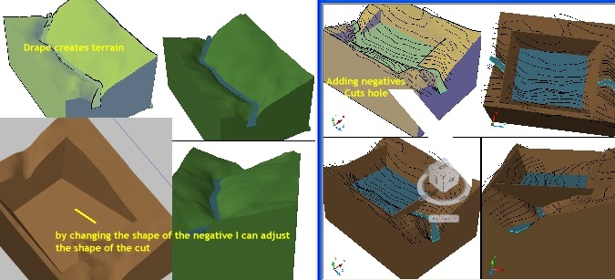
 You can use Mass Elements (using the DRAPE command)
 and then massgroups ( a command they continue to hide from the ACA interface unless you have one in the drawing already) to take the survey and turn it into a 3D site and then cut chunks from it using "Massgroups & additives and negatives" to change the shape. You can use the same to create more complex roof shapes.

This is what I did on a recent project to model a steep site for a pool desk and outdoor area so we would have a firm idea of how the levels would actually work. Using this technique, you always have the original slope untouched and can edit the cuts and fills as required. However it is always a 'basic hammer tool' and never has any real intelligence you expect from a aec package. It cannot then tell you how much cut and fill etc.
Here's a pic of a quick scheme for a dam I created and posted somewhere to illustrate how to use MASSELEMENTGROUPS to alter terrain without actually altering the original terrain. ie. Once you have created the terrain using the DRAPE command on your contours, you can then add a ME box as a negative shape to cut out the dam shape. The water of course is just a big box that is created to fill the entire model (not close to the edges though) so that it looks like it 'fills' the space to level, dam & river. Again though it really only serves as a make do for quick illustrations. I can't calculate how much capacity the dam has except to run the measurements of the cube I use for a negative and deduct how high it (it's not visible here) stands above the (high) waterline. Having said that, 20 years ago I am sure an engineer would have loved these types of tools. But, it is 2014.
I've used Autodesk Designreview to create video walk throughs and quite frankly the quality is embarrassing. But that's the thing with Autodesk. Rather than take a main product (like ACA) and develop it fully they would rather spend millions on a niche product, spend time with it, release it for free and then loose interest a couple of years later. Any time spent learning the product becomes wasted time as they've moved onto the next bright idea like a child with AHD. I don't want to spend my life learning your next bright idea software package. I need to earn money to support my family and our dreams. It's why I stuck with ACA and never 'upgraded' to the 'sweets' er.. sorry, 'suites'. I'm sure there is something useful in there but all I saw was paying more money to spend many hours learning a new software package so I can do what I do now. No thanks. Hence the learning about the stock market. I want to work for me & mine, not Autodesk.
As my teenage son takes over my pc and starts shooting his mates online I drool over the (realtime rendered) visuals that look at a glance like
photo quality movies. These are games obtained for well less than $100 and they often have tools to create your own environments. I've dabbled at times with the idea of importing models into Far Cry's CryENGINE environment so my clients can wander around enjoy gardens moving in the breeze, water flowing (no weapons) but my brain is swamped because ACA's WYSIWYG (1978) paperspace view no longer works in 2015 (finally fixed).
Here's a scene from Crysis and don't get put off - the buildings are supposed to look decrepid, it's part of the ambience of the game. This level of rendering, lighting & texturing is available and common in games today and some have probably passed through Autodesk software and remember! this is live realtime playtime rendering. It's a screen grab. No sitting for minutes or hours waiting to see if you missed modelling something.
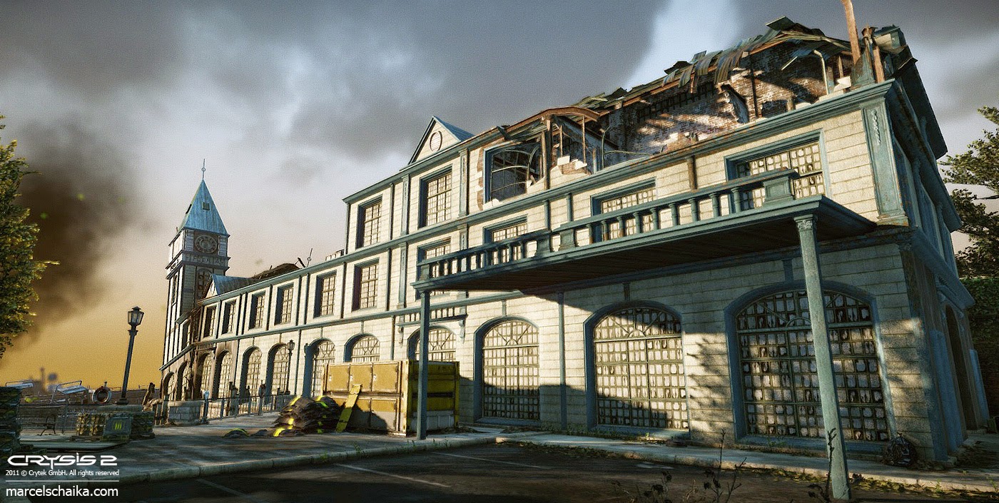
Imagine if we had access to this power of presentation somewhere in Autocad / ACA? Why not? Now I understand that CAD programs are much more accurate and operate differently but really, come on (aussie expression). It's only software.
In many ways I can see that Vectorworks is still catching up to ACA. Had ACA development continued it could be a very strong package. As always, the strength of Autocad (ACA) is it's flexibility and the weakness of Autocad (ACA) is it's flexibility. Sometimes you just want to be told what to do and not have too many options but power is well... power. But it does seem like for several years now, much more so with ACA, they have just played with the interface and the colours or given you yet another flawed way to do what you could do before. Little to no new real functionality. Certainly in ACA.
So .... yes I am still here. Many have picked up on my tips on the Roof Object and just maybe, one day, just maybe Autodesk will spend the money on upgrading this brilliant tool. The video's were a great way to illustrate lots of good stuff in ACA. Many great tips are still in my head. Maybe some can still leak out.
Hope you are having a rewarding and productive day.
cheers


