Saturday, June 12, 2010

Roof Object - I was WRONG again !!! Part 11

I can't believe it !!  I am flabbergasted.  This beauty of a tool was hiding yet another secret.  One that I said it couldn't do.  I don't think Autodesk knew.  EVEN the roof creator himself didn't know!!  But I am about to show you what we all missed - IT CAN BE DONE!

What?

This roof object (RO), that was created back for ADT1 can overlap itself.  Yes it's true it hasn't changed in all that time and it CAN do what we all thought it couldn't.  You just gotta know how to caress and seduce it.  Actually it's even Much easier than that.

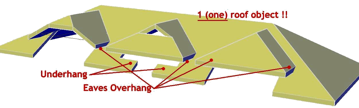
Take a look at these examples and see.  This picture is of just ONE RO.
I discovered this all by accident and there must have been someone else out there that also discovered this but perhaps because you have been told to explode to roof slabs you didn't bother to explore.  But my obsession with this clever tool continues to lead me to discover new tricks.

So how's it done.  Simply by creating extra edges & a gap which allows the object some space and you the opportunity to add an overhang or underlap. These gaps can be made smaller than you can see on a print.  


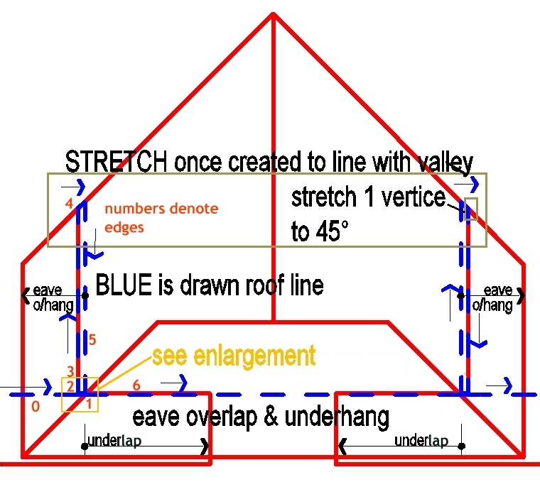
This example is the centre hip in the roof above. It both overhangs and underlaps itself.  I've shown the gap big enough to see but it can be very small and I turn this blue (eave) line off in display anyway.  The red lines would need stretching into position once you create the roof object but you would then have the RO valleys showing to know where to stretch it to. (It should become obvious if you do one).
Here are 7 edges from the LHS of the roof as numbered above.  I've pasted in each face slope so you can see it collectively.  You can see the whole hip has a higher pitching height (3200) to raise it above the surrounding roof.  You can see an extra 90d slope added to get the gamblet on edge 6.   The height for those egdes with 90 slopes doesn't matter much.  Here's the strange one.  The overhang to edge 1 controls the length of the underhang!  Sweet!


There's a number of different ways to create this shape but possibly one easy way is to draw a RECTangle over the walls that will hold the raised roof.  Offset a small distance (10?) and then again.  Stretch the top of the outside square down 3 x 10 to get the short 45d edge to line with the valley.  (ok I've not shown square distances above-sorry) You would need to lock your walls so they are not stretched and pref have everything else turned off.  This should give you enough points to snap to as you draw around. Erase the rectangles and STRETCH the top of the shape to meet the created valleys.

You will notice the created eave line snapback controlls the under/overlap width.  Drag it back & forward to see how it controls the extent. 

One more BIG tip when manipulating the Roof Object.  We are taught to pick vertices and drag along.  Good advice for everything else but for the RO, the STRETCH (S) command will give you more consistent results.  If an edge won't move, Stretch it instead.  This tip was fed to me by my young drafter who remarked "I can get the roof object to pretty much do what I like now!".

Ok to restress the rules;
- The Eave line cannot overlap itself but the overhang can but only with a gap between.
- I turn off the eave line as it doesn't represent anything I want to show on my drawings.  There may be times when the eave line path required to get the roof object as you want it is not what you want to show either.
- Stretch - don't drag vertice
-Odin Cary found that you may need to have no general overhang set for the roof to work at first so you may need to add overhangs later rather than set them as default.


-Don't forget you can add vertices by my Trim Trick if you need to add extra edges but it may well be quicker to recreate it.

Here is a closeup on how to get that overhang happening in another common situation. Here the secret is a simple gap where it overlaps.  Again the blue line would be turned off and you are left with a clean roof shape. I would stretch the inside snapback blue line to the left once created to line up with the forward ridge.  This will align the underhang with the main roof as you will see if you do it.


Once you get the hang of the rules these are dead easy to create.  How did we all miss it?


Oh dear...... I am going to have to go back and edit my earlier blogs !! agian!

BTW in case you didn't realise, in IE you can RC on an image and ask to open in another TAB and it will open a larger image you can more easily read.  You can also hold the CONTROL key and scroll your mouse to enlarge a web page display.Cheers
Roof On

Wednesday, June 9, 2010

Design Review 2011 - Walkthroughs??

What a disappointment this product is.  I'm sure some find it useful but after some excitment at the thought of the latest release, the blogs mentioning how lighting and the camera view has been improved, I was certainly let down when I tried it out.

I am comparing the product to ArchiCAD's Virtual Building Explorer which I think has hit bullseye as to what a program designed to give a client the power to virtually walk thru a design should be.  VBE is not free, costing around $600aus for the creation program but the low cost is more than justified by it's output.  This could really sell a design!  Conversely DR looks amateur.  It still can't properly light a model, materials wash out (still), it's view is still terrible, the interface is awkward and hard to manipulate requiring constant changing from one control to another. 

VBE does not require any software to be installed for the end user.  They receive an executable that simply opens an interface to run thru the model.  Navigating is familar to anyone who has ever played a 3D game.  WASD keys forward-back, left & right whilst 'looking' with your mouse.  It's very easy to walk around and look.  DR is just pathetic in comparison.  It can't move sideways whilst looking forward so you can't walk past a building while looking at it. (just dumb). VBE has used OpenGL rendering to produce a game like environment with materials and lighting that look... well like quite a good game.  DR's environment is gawky and ugly.  How come Graphisoft can get an easy camera view inside a building but DR's is like a fish eye camera with bad distortion all round?

I'm sorry but there is just no comparison between the 2 programs.  VBE is professional and very impressive.  DR is like something developed by a back yard operation.  I don't get how Autodesk could miss the mark by so much.  VBE has been out for years.  Graphisoft purchased the technology when they bought a company and they have really used it well.  I'm told that Adesk also had "Walkthrough" back in the 90's but they dropped the ball and have not picked it up.  Perhaps they thought that DR was meeting it but anyone who thinks so has not checked out how high Graphisoft have raised the benchmark.  I am very frustrated and embarrassed that DR is the best I can offer to the sales team. 

Visit the VBE site and download the samples at the bottom of the page and then make some noise on the newsgroups or directly to Adesk.  I don't think they see any need to compete.

Adesk have committed themselves to a crossplatform approach and the navigation tools are used in many Adesk programs such as Autocad, Max, Maya, Design Review, Navisworks, such that you can open an unfamiliar program and understand how to navigate a model.  Sounds good but the tools they chose to incorporate are just plain awkward.  Difficult to use I would not like to give them to a company director and watch him embarrass himself trying to move around and look about.   The navigators are the wrong choice.  Have none of the programmers have ever played a 3D game?  How easy it could be. Was it an executive decision by the power brockers?  Instead they designed a convoluted system that requires training to operate.  After a few hours I have can navigate somewhat successfully but it's still not freedom.

Sigh.  If you pop in to Adesk development it appears there's nothing good on the horizon either.

Wednesday, June 2, 2010

Auto Title Blocks & Fast Plotting

If you are doing large projects in ACA or just Autocad you should be making use of the PN or the SSM (Sheet Set Manager) which automates the numbering, labelling and naming of files and compiles a title sheet for you.  Hawever if you are working on smaller projects this may seem a bit overkill.  I wanted to share some available tools that can be used that will bring great efficiency if you are only using a 1 file approach (even multistorey) as I do.  I do use x-ref's, keeping the survey and entourage seperate (and maybe others) but essentially I draw and set up plot sheets in the same file using paper space tabs.

Template
The big one that saves you time is using a template with all your settings already installed and maybe some basic styles and componants.  Your text & dim styles, layers that are not created by your layer key standard (non aec entities).  (I cheat and grab a similar project.)   I start my model at 0,0 (floor plan or site plan) and when I flip to my floor plan sheet it's viewport is ready to print (maybe a little tweaking).  I put my elevations in the same place each time and they also will be ready to print from their layout.  This also allows for the correct layers to be already set so selecting the Electrical layout will show the plan already in Reflected display rep and have text and dims turned off etc.  For two storey, the right layers are set in each floor plan along with the correct cutplane and display rep (see my 1 file multi-storey approach).

Fields
First, hopefully you have been using fields to derive automatic information useful to list on your drawing sheet.  Fields such as Date Plotted will automatically collect the plotted date and insert it into your drawing and be updated each time it's plotted.  I often store drawings in pdf format for others to utilize and that pdf will clearly show it's plot date so plotted sheets can be compared.  It also shows the file name of the drawing file so we know which file it came from.  There are many fields that can be used in your title block or anywhere in the drawing, even if you don't want to display it.  Some may only need to be viewed by the CAD drafter.  (You can see here I was using ACA2011 and it was constantly crashing - you can see 'recover' in the file name.) By default Fields will show with a non printing grey background so you can tell them apart from normal text.

To insert fields go to the 'Insert' menu or under the 'Annotate' ribbon and the extra pulldown.

But you can also create your own....

Drawing Properties
Here you can set up fields to hold the custom data you require to access in your drawing.. 
In earlier versions you can find this under the File menu or by clicking the tiny arrow bottom RHS of screen, typing _dwgprops or in later versions under the Big A

I have created up a series of fields that can then be accessed by the title block for each sheet.  The advantage of using DP to hold your data rather than entering directly into your title block block is that it's much quicker to edit and access.   It's also accessible as fields and can be referenced in more places than one.  Where I have a client name, I can have that field entered into my title block as well as sheet set cover in a different font and setout all in my template file.  Can't do that if entered straight into your title block.  Open a template, save as new job, enter client name once and it appears on every sheet title block AND the cover with only the one entry.  Spelt it wrong?  Update quickly once and be confident that everywhere it appears it has been corrected.

CTAB
Another not well known trick here is to use the 'ctab' field inserted into the title block to reference the name and number of each sheet.  The CTAB field reads the name of the layout.  Now you only get one reference here for each layout but I put a space between my sheet number and the sheet title and I can use some old fashion fudge action to split them into 2 parts. 
Use of a 2d solid object effectively blocks out the parts I don't want of the same field 'ctab' used twice as shown here.  You could use a solid hatch, wipeout, aecpolygon or such for the covering but they all have issues.  My 2d Solid is slightly off white 255,255,254 and has a 'Standard' plot style assigned (STB) as to alway print the colour white regardless of the plot style used.  The beauty here is the TAB name doubles for organising your drawing as the layout names are visible when you are working. You can see that here I haven't entered the site size or the R coding yet.

I would love to be able to gather the tab names together for a sheet list but I don't believe this option exists except maybe thru some clever programming. 

Another benefit to this method is that when printing a layout to a pdf, Acad assumes the dwg file name and appends the layout name so I will get ClientName-Poolhouse-02-FloorPlan.pdf as the default name to save which returns a nice set of pdfs.  Not useful if you print multi sheet pdf's but they can be difficult to email especially if the recipient only wants the site plan.  To be honest, Acad is somewhat random here and does not always assume the full name - but most times.  It also doesn't appear to work in AcadLite.

Draw Once
I adopt a Draw Once philosophy to my drawings (where possible) to reduce the error factor.  We all make them but if we can minimise the times we draw something it will reduce errors especially when changes are made.. 
If you are labelling each title block individually then you are doing a lot of extra work and not making use of the software effectively and greatly increasing your chances of errors.  If a clients name is spelt wrong, it would take me about 30sec's to open a dwg file, change the name once and send a whole set of drawings to a printer (real or pdf).  The use of a field fills in the project details in the title block but also on the cover sheet in a completely different font & size. I can even do something arty by doubling it up and fading the 2nd one behind for a shadow effect.

Plotting
By using clearly labeled layers and discipline to what goes on them we can reuse the same drawing for different printed sheets turning layers on/off.  Here is Australia, smaller practises layering is atrocious and few follow any sort of good practise.  Unfortunately If they do have a good office scheme then getting drafters to follow it is another difficult task.

Page Setups
If you aren't using these then you have to read these links.  (Still picking corners??)  This tool makes plotting SO much easier and who likes to spend time plotting?  Once setup, this makes it easier to print either a hard copy or pdf set, print a half size set or print to a different printer at a few clicks.
Archidigm's page setup tips
Ellen Finklesteins tips
Cad Geek - Importing page setups
Heidi Hewitt

I have some other practises that might be helpful.

Metric or Imperial
If you are a metric user, make sure you are using metric templates, your own or Out Of The Box.  MEASUREMENT should be set to 1 for metric and this forces Autocad to reference metric linetypes and hatch files (Acadiso.lin ad Acadiso.pat).  I often get .dwg files that have a setting of 0 and they will reference the imperial files and it can be difficult to get dashed lines and hatches to display correctly with your drawing.  To correct, you need to set Measurement to 1, reload every loaded linetype and regen.    Depending on how the linetype was scaled can effect the outcome.  Linetypes should really be drawn a 1 scale although you will have to adjust the useful 'batting' linetype to the size required.

Now here's where I seriously divert from recommended practise.  I set LTScale to 25 and leave it.  I don't change LTS or think about it.  I set my Paper space layouts PSLTSCALE to 0 which removes dynamic adjustment of linetypes but for residential work, using the common linetypes like dashed, hidden, Centre, Dashdot, EvenDash, Divide (and even iso02100 dash space) will produce reliable results that just work.  I mostly do not consider scale on linestypes.  As I see them in model space is how they will print in paper space and I don't have to remember to set LTS back to 1 to print.  For the scale used in residential work (1:10,50,100,200) this all works perfectly. (let me know if you want to see a file of this working in practise).

Of course this is old advice with the new MSCALE setting which dynamically adjusts according to the set annotative scale but I prefer my simpler and reliable practise. If you do larger work (commerical) then learning the MSCALE setting is a must and will make the whole linetype scale problem go away (at least that's what they tell me).

Now ducking for cover!

Cheers