Friday, January 15, 2010

Roof Object part 9

(Yeh I know, like a dog at a bone....)

I just had to post this little gem from Sergej. He emailed this cute cottage pic showing a portion of roof that neatly meets into the main roof without influencing it.  Notice how the entrance roof joins into the roof on the left but there is a portion of the main roof behind that continues as though this lower roof is not there.

This doesn't work with the ACA Roof object  I had no ideas about how to get this to work except using a separate object and trimming them around each other. Trouble is how to work out where to trim and how to keep the slopes correctly orientated.
How about this! In Sergej's Spirit roof object using his 'sub-roof' , Sergej can get the minor roof to nestle in there like a suckling lamb and muma bear is just as sweet as. (Sorry about mixed metaphors an' all). This is all done with a few minor clicks and is a simple affair. Here's a pic of the Spirit Roof shown against the ACA Roof Object's effort.

Autodesk please let him have another go at the roof object.  With all the time he has spent honing his roof programming skills he could give some great upgrades to this roof object tool.

Here is another not uncommon situation where Sergej's updates to the Spirit tool would be great if they were available in the ACA Roof Tool.  Here I show an octagon roof that nestles at the corner of a hip roof. Using the RO, we have no way of adding the extra slopes because they are inside the controlling edges.
UPDATE: See youtube video where I describe how this CAN be done using Odin's MODELEXPLORER trick
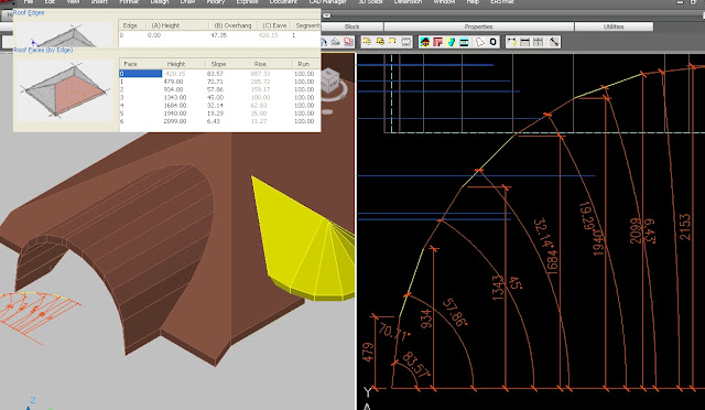
Here is a coloured view showing showing the Spirit roof with a Sub-Roof object.  I've yellowed a portion of roof that has no controlling lower edge that's perpendicular to the slope as you require in ACA (including the aecSlab Object).  I could see that I could use a second roof and trim it to shape but the slope is hard coded to be perpendicular to your edge so it's going to fall apart!


I might come back and have a look at how to work out the trim lines on the 1st roof I've shown here but as a hint, it involves constructing the 2 roof's ensuring they are interlocked and taking a snapshot in plan view (hidden line) to get the right roof lines and using those as trim lines. The connecting roof' edges will have 90d slopes.  We could do the same for the 2nd example I show here if I leave tiny 90d to slope control edges and hope no one notices.

Sergej tells me that with his Spirit sub-roof, he can create the 2nd roof and have it automatically calculate how it interacts with the main roof, subtract the overlapping portion and still maintain all it's slopes.  What's more it can be amended and still update correctly.  I assume it remembers the original trimmed perimeters.  Oh to have that in ACA!!  Yes please!   UPDATE: It was thinking about Sergej's explanation of his sub-roof mechanism in his Spirit roof tool that brought me to the understanding of how we can do it in ACA. It's the same way just not automatic like his Spirit tool. I'm sure you could resolve the first example I've shown here as well using this method. 


Another problem solved with the ACA / ADT roof object !!!!!!!!!!

Tuesday, January 5, 2010

Roof Object - Part 8 - getting round it!

continuing my rants on the ADT/ACA Roof Object (not slabs)... (see all roof object posts)

Creating a Round roof
I'm sure you know that you can create a round roof, either as a complete circle or as part of an overall roof. When you select a round roof, each arc will be an edge with 2 end points and a mid point even though you may appear to have many hips. You can change the appearance for the smoothness of the curve (& number of hips) by editing the edge (Selecting the Right Roof Object and Right Click option) and increasing or reducing the number of segments (max 30) to represent the curve. Whilst 30 may look the smoothest in real terms, a round roof is built with a number of segments (hips) so you may be best to match the contruction number for an accurate representation.


There doesn't appear to be any way to create a curved roof using the command line but you can create one by applying the Roof tool to curved linework or walls. Note that ;
  • You cannot create a completely round roof from a circle linework or 2 Arcs so use 2 arc'd wall objects (2 arcs - because you can't create a completely circular wall with one wall either!).
  • You possibly can't create a roof with a round portion from linework unless it's a closed polyline. (Well that's how I had to do it).
Curved roofs

You can also create curved roofs in the vertical plane for barrel vaults, eyebrows and igloos. You can't create a smooth curve but can add multiple changes in pitch to approximate the curve which again is how they are generally constructed in real life. Now the effort to add these multiple pitch changes is no small task so you would like to know how the resultant estimate 'curve' will look before you begin to ensure you are going to be happy with it. Also you need to be able to enter exactly each pitch and height changes to get the appearance of a constant curve not spend all day guessing at the numbers? So how?

Well I have a simple idea to give you the exact data to be entered in the roof edge to get exactly the result you were expecting.

Draw your Arc in elevation view as it would appear adjacent with the model. Use the DIVIDE command to place Points around the Arc. Use an even number to land one point at the apex if you drew the whole Arc (I only drew half!). . Draw a PolyLine on a different layer joining the Points and then turn the other layers off. You should now be left with the Polyline stepping around your curve and be able to estimate whether you are happy with the resulting estimation of the curve. (This will be on your aecElevations as well as any rendered model.) If not - erase the points and use the divide command again increasing the points if you want a smoother curve. Once satisfied, you can dimension each point by angle and height as shown above and this will give you the numbers you enter into an edge on your roof object. OR... you could simply draw a polygon instead of the PLine and have your segments a lot quicker! Again adjust the number of sides until you are happy and then use the procedure above to measure each point to enter into your RO. He's pointed out this is also useful for Roman & Gothic arches. Thanks for sharing this cool tip Robert. As James points out, you can also attach an edge profile to an aecSlab to create the curve. Your slab would be a very narrow ridge at the apex and the curved profile both sides would give you your round roof. You can trim slabs with a pline to fit it into your main roof.

TIP: Be aware the height numbers are for a roof object with it's elevation at 0. If you need to adjust for a different baseline of your roof object, stretch all your dimensions (not the angle ones) down or up at once if necessary to add/delete any extra required.

With this technique, you can create an Eyebrow roof out of a normal gable roof as illustrated, or a barrel vault roof or your own special creation etc.

There is a limitation of the roof object shown here for the eyebrow roof. The Roof object thickness stays perpendicular to the main roof pitch and does not dynamically adjust with the changes in pitch as shown in the picture. For me this would be covered by a gable end treatment (Structural object) but would also be evident in any section. (Note that Sergej's updated Spirit roof tool has no problem with keeping the roof thickness constant!)

Inverted roof
You can also create a Concave or Convex (bullnose) curve to your roof though I may use a wall style for these (see here and here). The other option as James has shared is to add a profile to a slab object so the slab itself is only a very small postion and the curve is achieved with the profile. Very easy to do if your roof line is constant.


Copy & paste Trick (sergej's tip)
If you are looking at doing multiple pitches to more than one edge with the ACA Roof Object as shown above, it can get tedious real quick entering each height and pitch on a number of edges. However once you have entered a series to one edge, if you click in the first column of the face box and Control C to copy, you can then move to another edge and paste the same numbers (yes all three columns). If you had originally selected the 2nd (or more) edge already, it will be available in the dialogue box to paste to. Ok it's not perfect. Be nice to be able to alter a number of edges at once but it's quicker than doing each edge individually. Oh and it is a little temperamental sometimes and may need caressing to get the paste to overwrite.

Oh didjaknow?
  • When you create a roof object, it remembers the last pitch for next time but not the last edge cut. (I think it writes it to the registry!)
  • Once you edit some of the edges, adding gables etc, you may not be able to edit the main pitch via the properties pallete and may need to edit each edge at a time! Sigh! Therefore it may be quicker to remove a pitch (gable?) adjustment, change the roof pitch and then re-enter the gable.
Cheers!