Saturday, July 17, 2010

Get Rendering

I have a number of posts about my own experiences rendering inside ACA.  I held off using 2007,8 and 9 because I had a quick and efficient system with ADT2006 but I have been enjoying using ACA2009 for almost a year now.  If you are not rendering then you are missing out on the fun.  I thought it would become a slow labourious process with overnight renders and the nightmares to go with it but I've found it almost as quick and efficient as it was in 6 and of course the new Mental Ray rendering engine can produce a higher quality finish.

As a side issue I have discovered that a number of OOTB practises of ACA are detrimental to an efficient process, namely the overuse of MassElements within styles, the overuse and underuse of Render materials and of course the use of the Project Navigator or even X-ref's.  Not that I don't use X-ref's but if you do you have a number of extra steps to go thru to edit files in preparation for rendering.  At best it's clumsy and verbose (but maybe necessary for larger projects) hence my development of multilevels in one file.
So..with the acceptance that I'm no expert renderer and that there are few that are on rendering inside ACA I would like to offer the tips I've learned to get a little something out of this baby.  If you are after the highest quality renders, then Max may be your gig but if you would just like to get a basic good quality render out quickly and efficiently without paying the premium in time and upgrades for another program then you can get there with AutoCAD and ACA.  You also have the advantage of being able to alter the file and re-render without having to learn & link to another separate program.

In ACA assigning materials is a step sideways from the direct approach in Acad which assigns materials directly to an object or bylayer.  With the styles manager and it's matrix it can be a little more complicated.  But that's ok.  Unlike Max which is a dedicated renderer and not much else, you can use the same file for preparing your Development Application and rendering and still rip off quantities so changes need to be only done once.  You could progress the same file to construction drawings and even still use it for rendering at a moments notice!

Here's some links which may be helpful on learning about Acad rendering but also try google.
http://www.dailyautocad.com's%20e-book%20%22creating%20render%20materials%22/
http://alt.dailyautocad.com/files/2009/2009-011-mat-def-toolbar.zip
http://www.dailyautocad.com/2006/01/autocad-tutorial.html#render
Archidigm article on Materials
Archidigm's Development Guide (look up materials (P1) and the appendix at the end for render/materials)

Firstly it's good to get your head around the use of aecMaterial definitions.  That's not just for rendering though they contain the link for any render materials as a part.  aecMats are used to describe how a material when applied to an aecObject will display in any of the display reps (Presentation, Medium Detail, Reflected etc) and in any view (plan, elevation, model etc).  This would generally be understood as a hatch pattern, line thickness and possibly colour shading.  However within this definition set you can also assign a render material (RMAT).  Here I have developed my own thoughts apart from the OOTB system to reduce the number of RMATs used which will quickly bring your system to a crawl, especially if you are still using a 32bit OS.  I also work on more low end stuff and have no time to fiddle and tweak too much so I need a system that will allow rapid development and render.  It's not uncommon for me to start a design in the morning and finish the day with a set of presentation drawings (site,floor plans, elevations) together with a smart render for the cover sheet.  With my multistorey in 1 file approach this has become much easier to achieve.

As for the overuse of MassElements I have discussed that here but in case you didn't get it I'll say it again here.  You don't always need to use a ME for an object (block) that you embed into a style.  I used the example of the aecDoorPanel that's OOTB but here's another example. 

My young partner who is new at ACA created a letterbox MultiViewBlock.  He created a model and 4 views (Plan,Side,Front,Rear).  For the model he used MassElements and for each material created an ME style and then created seperate render materials that were captured in aecMaterial definitions.  Now he did a great job and followed ACA methodology but adding this letterbox into a file added a swag of render materials, aecmaterial and ME style definitions that quite frankly we didn't need.  This letterbox comes in a series of colours but apart from that there are no choices and it's going to look the same in every instance.  So here is what I did to make this object a much more friendly object. 

Editing the 3D model I turned every ME into a 3DSolid using the Right Click option.  I edited the Render Materials so I only had RMats I would typically have in my file (and is on the limited list of materials required).  The cast concrete letterbox can use the same render material that's used for rendered walls (a sand finish render).  The steel letter recepticle can use Paint-SemiGloss though really do you really need to see shine on a letterbox (and add the associated render time).  In the Style manager, using the 'Broom' button sweeps away the no longer required ME styles and aecMaterial styles.  Purging the file removed the unwanted RMats.  I make sure there are no layers in the file and all is on layer 0.  The command "SETNESTEDOBJECTSBYBLOCK" (alias'd by me to FB) rids all layers,colours, plot styles, linetypes, and pen thickness's but leaves the render material assignment assigned.  LAYDEL will remove unwanted layers that won't go.
Now both 'Paint-SemiGloss' and 'Render' do NOT have any colour assigned.  That comes from the object being set to 'ByObject'.  This means that when placed in the drawing I can pick the MVB and without exploding set a colour if need be. (I use aec Standard.stb plot style where colour is meaningless unless told otherwise).  
So now my letterbox can be dropped into my drawing on a layer of my choosing, coloured if required, rendered, all with a light touch and minimum fuss.  Any item that is a specific colour like the backplate is given that colour in the original block (after using FB of course).  You can see you get one selection for colour so it won't work where you need two.

Oh the ME's?  Well if my letterbox was an ME I would have to dive into styles and search thru menu's to find which style was assigned and if ByMaterial, then trace thru the material settings to find the colour.  Now for a wall or roof I use this 'style' process (not always) but for peripheral items (props) like letterboxes it's just so much overkill and takes 10x as long to manipulate.  Dump the ME's and just use plan ol' 3DSolids.

Have you downloaded a block and found lots of weird colours?  I downloaded a speed boat that I've never used.  This one had lots of render materials for seats, chrome, engine parts and nice colours assigned for the paint and the flames.  However the acad model itself was all green!  Now making an entity a colour is simple but years ago we might have followed an office assignment.  Colour 151 = chrome and Colour 204 = red leather etc.  But we don't need to follow such an indirect scheme.  Make the object the desired colour and the chrome silver and then assign RMAT's that have colour ByObject.  I also removed all the layers (no need to assign material ByLayer either).  Now if I ever use that speed boat in an image it won't add any layers, (new) RMATs, plot styles or, linetypes  If I make the body ByBlock I can even colour it when added to the drawing without exploding the block and it has Paint-HighGloss applied so I get a great spray job as well.

It's a prop!  Who wants to spend time fiddling with a boat? You just want to drop it in your drawing and it behaves and stays quiet!  I've used this technique for the car in this image. The car is dropped in (the body is white or whatever the layer 0 colour is) and a colour selected).Now it ain't going to win me any rendering awards but it has won the client over.


If you've had a chance to check out the even newer Mental Ray rendering engine update in 2010 and 11 it may have a high drool factor - the new materials look lovely, but it's going to slow you down and weigh down your system and prevent you from an efficient process.  Check out the paint colours.  Each colour has it's own RMat !! That's a lot of Rmats.  Ditch the colour, make it ByObject and then you can use the same RMat where-ever you use that same gloss level.  And remember unless you are trying to create a high image level, then many of the subtle variations in paint are lost on a simple quick rendering.  Is gloss plastic that much different from Gloss paint.  If you think so then you shouldn't be reading this article.   If you require a specific material like brickwork then yes you will need a RMAT for each different one though for something like concrete pavers you can simply use a bump map and colour ByObject again.

Odin Cary of Archidigm is doing some great investigation articles of ACA2011's new rendering and materials and it seems he's having better luck.  He also has explained the 'jump to perspective' bug that had me in frustration.  Odin has also started renaming the complex and longwinded material names so I am not alone here.

Also be aware I am talking exteriors here.  For interiors the game changes alot.  Rather than the one light source (sun) you need the reflective values of many surfaces to realistically light an interor but to be efficient you can still greatly reduce the number of RMat's used by using the above techniques.

Get in and render!  (or simply!!  then render :-)

Friday, July 9, 2010

Multiple Levels in a single Drawing File? Part 2

Ok so are you interested enough to read further on this idea?
I can promise a productivity boost on residential and small commercial projects.  Following the OOTB processes can at times lead to a lot of the confusion attributed to ACA/ADT when simpler processes could have been put in place.  The OOTB processes are also detrimental to efficient production especially when you want to turn (churn) out fast renders as well.

Here is the recipe on how I achieved it and it was much simpler than I thought it would be. So simple that I ponder why Autodesk hadn't provided this as an option.  Oh and this is just background of how it works.  You don't have to understand or recreate this.

Let's go to the the list of the items I posted in Part 1 in more detail.

A Layer Key Style that holds a Layer designator.
We all work differently and we need to have the items required for our environment. For very large projects, you may have multi disciplinary drawing files but for the most part, I would complete my set of architectural drawings and a structural engineer would complete his own set of drawings. Maybe a hydraulic engineer would be required or perhaps a civil engineer but they would also complete their own set of separate drawings (& CAD files). So there is no need for me to preface a layer with an A.  I preferred the level indicator to be first and I use a simple number. '1'. It's great to open the layer dropdown and type S and go straight to the Site-* layers. But it doesn't really matter because as long as your level indicator is in the same place you can use the '-layer' command to find and manipulate your layers. So 'A-Wall-L1' or 'A-Wall-FLR2' is ok. Because the layer manager dropdown display is so narrow and only shows a limited number of letters I try to keep mine simple. You cannot mix A-Wall-L1 and A-Wall-Blow-L2 though as the level indicator is in 2 different places (3rd and 4th along) (In my system anyway).

(Odin Cary of Archidigm has excellant explanations on all things ADT/ACA in his Development Guide.  Check out under section 2 for Layer Key Styles.)

As an explanation;
From the command line I can issue -layer , select 'OFF' and then using a wildcard such as 1-* have all the layers starting with 1- turning off. (The * being a wildcard for those not familiar). I could also issue *-*-FL1* but of course it will fail if the level is not in a consistent position in your layer names. If the level is always in the 3rd position it should work. Therefore I chose to put it in the first position and also allow me to sort my layers naturally by level.
(I've seen a wish list item posted several times to allow layer groupings, but this is not available at this time).

However this does not prevent me from sorting via major item either. Issuing the -layer command again and OFF and *-Wall* would turn all wall layers off regardless of their level.
So from this basis we can turn all layers off using the * wildcard and then turn back on those we want to work with. Therefore in lisp fashion the following lines...

(command "-LAYER" "m" "0" "F" "1-Elec*" "OFF" "*" "N" "ON" "1-*,1+*" "")


...sets layer 0 as the current layer, freezes the electrical layer (as I only want that one on when doing electrical layouts), turns all else off, then turns on the level 1 (and 1+) levels (except the frozen electrical layer).

My system uses the difference between freeze and off for layers. Frozen layers do not regenerate and reduce the load on the display system. Off layers are generated though not displayed and are quickly turned off & on. So by freezing layers I don't want to see for a while and turning off layers I might want to edit quickly in my next move, I can have a fast responsive system.

I used the 1+ Stair for items that would span more than one level so they would show also on the 2nd floor as well (but with a different cut plane and display rep - more on that one later).

So if we tie the above lisp line to a simple command, say 'L1', then we have created a new command to show us all the layers on level 1 only. More on this layer..er...later.

I also use other 'level' indicators to sort layers such as Site-, 3D- for info only used for modelling or elevations and not required in plan views. Your Layer Key Standard will set whether your layer names have to follow a strict or loose convention. Some LKS's have strict 1--4-4-4 numbers of alphanumerics generally with the last 2 places being optional. Mine has no restriction on the number of each. I find the AIA layering system, designed to organise a hospital complex way overkill for simple residential so don't feel tied to such a system if it's not needed. 

Hey try this. If you have an x-ref in your drawing, use the layer command to freeze all it's layers like this -layer F X-RefName|* The | symbol is shown in the layer name itself in the Layer Manager between the x-ref name and the layer name (inside the x-ref).   I have my survey as an x-ref named 'Survey' and using this info I can freeze all survey info in my drawing using lisp.

All new to you? Open your Layer Manager and click on the 4 buttons top right. I'll try to add some good links here for simple tutorials on these great and powerful tools.

Can you see why I have dropped the A- from my layer names. Layers are sorted alphabetically (of course) and you can use this fact to your advantage in your layer scheme. Even keeping your A-, what comes after will determine the sorting order.  In the layer box you can type say 2 and it will scroll to all my 2nd floor layers.

Place to hold your elevation floor level heights.
If you want to switch to the 2nd floor, you need to be able to draw a wall at the 2nd floor height. This height needs to be entered and available to the drawing. I did want to use Fields but as yet I don't know of a way to access them in lisp (strange!). It needs to be saved with the drawing but it's not a drawn entity.  So for the moment I have elected to use Autocad variables (thanks David Koch)  Acad has 10 user set variables available that are stored in the drawing when closed that I can enter and access.  I chose the interger based as I work in mm and won't be requiring any decimal places. If you have decimal places in your floor heights, you will need to use the USERR1-5 system variables as the R stands for REAL.  I assume level 1 at z=0 but level 2 is set in 'USERI2" and level 3 in "USERI3" etc (the 'I' here is an i). My loaded custom autolisp file reads this variable when I open the drawing and assigns the variables FL2 and FL3. These variables (FL2/3) will be lost once the drawing is closed hence the use of the system variables to hold the values over.  An easy way to access these is thru the 'System Variable Editor" available under the 'Express Tools' under 'Tools'.

Now don't worry if this is all confusing to you. I am just trying to give some background info on my method of madness. I can send a template or sample file to you that has these items set up already and I have followed OOTB methodology as much as possible so that I have minimised my customisation. My overriding rule is to Keep It Simple so I assure you it's not complicated.

Next .... Cutplanes, Zplanes and switching Display Representations.

Tuesday, July 6, 2010

Free ADT teaching vid's and other news.

Daryl Gregoire of CadClips has just released his ADT and Autocad video's for free viewing.  Looks like he stopped teaching at version 2008. Not too much has changed since then anyway.   I have had CadClips link on my page for some time so you may have already visited but if not pop over and you can get an online video review of that difficult to grasp concept. 

Perhaps watching someone do it will be the thing that gets it to sink in!  Watch them here

(pssst  you will even see some Revit video's too but you won't here it from me!

Matt Stachoni is a heavy weight in the installation and setup of AutoCAD Architecture and it you have some questions on how to install and where, his guide, available at his new web site aecblog will make a good night time read.  (At the time of posting this it was off-line but come back to it).  I only do single installations so all the network stuff was more than I needed but I enjoyed his hints at how to hack the dialogue boxes.  You know when you have to keep enlarging them EVERYtime and it gets old.

and in some interesting news Dell Not so Swell

Is there any company that's reliable and trustworthy to deliver and full working product anymore?

cheers

Saturday, June 12, 2010

Roof Object - I was WRONG again !!! Part 11

I can't believe it !!  I am flabbergasted.  This beauty of a tool was hiding yet another secret.  One that I said it couldn't do.  I don't think Autodesk knew.  EVEN the roof creator himself didn't know!!  But I am about to show you what we all missed - IT CAN BE DONE!

What?

This roof object (RO), that was created back for ADT1 can overlap itself.  Yes it's true it hasn't changed in all that time and it CAN do what we all thought it couldn't.  You just gotta know how to caress and seduce it.  Actually it's even Much easier than that.

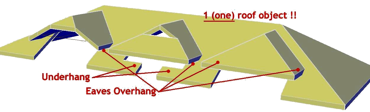
Take a look at these examples and see.  This picture is of just ONE RO.
I discovered this all by accident and there must have been someone else out there that also discovered this but perhaps because you have been told to explode to roof slabs you didn't bother to explore.  But my obsession with this clever tool continues to lead me to discover new tricks.

So how's it done.  Simply by creating extra edges & a gap which allows the object some space and you the opportunity to add an overhang or underlap. These gaps can be made smaller than you can see on a print.  


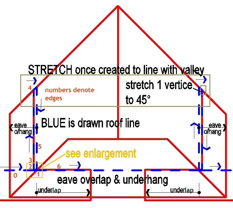
This example is the centre hip in the roof above. It both overhangs and underlaps itself.  I've shown the gap big enough to see but it can be very small and I turn this blue (eave) line off in display anyway.  The red lines would need stretching into position once you create the roof object but you would then have the RO valleys showing to know where to stretch it to. (It should become obvious if you do one).
Here are 7 edges from the LHS of the roof as numbered above.  I've pasted in each face slope so you can see it collectively.  You can see the whole hip has a higher pitching height (3200) to raise it above the surrounding roof.  You can see an extra 90d slope added to get the gamblet on edge 6.   The height for those egdes with 90 slopes doesn't matter much.  Here's the strange one.  The overhang to edge 1 controls the length of the underhang!  Sweet!


There's a number of different ways to create this shape but possibly one easy way is to draw a RECTangle over the walls that will hold the raised roof.  Offset a small distance (10?) and then again.  Stretch the top of the outside square down 3 x 10 to get the short 45d edge to line with the valley.  (ok I've not shown square distances above-sorry) You would need to lock your walls so they are not stretched and pref have everything else turned off.  This should give you enough points to snap to as you draw around. Erase the rectangles and STRETCH the top of the shape to meet the created valleys.

You will notice the created eave line snapback controlls the under/overlap width.  Drag it back & forward to see how it controls the extent. 

One more BIG tip when manipulating the Roof Object.  We are taught to pick vertices and drag along.  Good advice for everything else but for the RO, the STRETCH (S) command will give you more consistent results.  If an edge won't move, Stretch it instead.  This tip was fed to me by my young drafter who remarked "I can get the roof object to pretty much do what I like now!".

Ok to restress the rules;
- The Eave line cannot overlap itself but the overhang can but only with a gap between.
- I turn off the eave line as it doesn't represent anything I want to show on my drawings.  There may be times when the eave line path required to get the roof object as you want it is not what you want to show either.
- Stretch - don't drag vertice
-Odin Cary found that you may need to have no general overhang set for the roof to work at first so you may need to add overhangs later rather than set them as default.


-Don't forget you can add vertices by my Trim Trick if you need to add extra edges but it may well be quicker to recreate it.

Here is a closeup on how to get that overhang happening in another common situation. Here the secret is a simple gap where it overlaps.  Again the blue line would be turned off and you are left with a clean roof shape. I would stretch the inside snapback blue line to the left once created to line up with the forward ridge.  This will align the underhang with the main roof as you will see if you do it.


Once you get the hang of the rules these are dead easy to create.  How did we all miss it?


Oh dear...... I am going to have to go back and edit my earlier blogs !! agian!

BTW in case you didn't realise, in IE you can RC on an image and ask to open in another TAB and it will open a larger image you can more easily read.  You can also hold the CONTROL key and scroll your mouse to enlarge a web page display.Cheers
Roof On

Wednesday, June 9, 2010

Design Review 2011 - Walkthroughs??

What a disappointment this product is.  I'm sure some find it useful but after some excitment at the thought of the latest release, the blogs mentioning how lighting and the camera view has been improved, I was certainly let down when I tried it out.

I am comparing the product to ArchiCAD's Virtual Building Explorer which I think has hit bullseye as to what a program designed to give a client the power to virtually walk thru a design should be.  VBE is not free, costing around $600aus for the creation program but the low cost is more than justified by it's output.  This could really sell a design!  Conversely DR looks amateur.  It still can't properly light a model, materials wash out (still), it's view is still terrible, the interface is awkward and hard to manipulate requiring constant changing from one control to another. 

VBE does not require any software to be installed for the end user.  They receive an executable that simply opens an interface to run thru the model.  Navigating is familar to anyone who has ever played a 3D game.  WASD keys forward-back, left & right whilst 'looking' with your mouse.  It's very easy to walk around and look.  DR is just pathetic in comparison.  It can't move sideways whilst looking forward so you can't walk past a building while looking at it. (just dumb). VBE has used OpenGL rendering to produce a game like environment with materials and lighting that look... well like quite a good game.  DR's environment is gawky and ugly.  How come Graphisoft can get an easy camera view inside a building but DR's is like a fish eye camera with bad distortion all round?

I'm sorry but there is just no comparison between the 2 programs.  VBE is professional and very impressive.  DR is like something developed by a back yard operation.  I don't get how Autodesk could miss the mark by so much.  VBE has been out for years.  Graphisoft purchased the technology when they bought a company and they have really used it well.  I'm told that Adesk also had "Walkthrough" back in the 90's but they dropped the ball and have not picked it up.  Perhaps they thought that DR was meeting it but anyone who thinks so has not checked out how high Graphisoft have raised the benchmark.  I am very frustrated and embarrassed that DR is the best I can offer to the sales team. 

Visit the VBE site and download the samples at the bottom of the page and then make some noise on the newsgroups or directly to Adesk.  I don't think they see any need to compete.

Adesk have committed themselves to a crossplatform approach and the navigation tools are used in many Adesk programs such as Autocad, Max, Maya, Design Review, Navisworks, such that you can open an unfamiliar program and understand how to navigate a model.  Sounds good but the tools they chose to incorporate are just plain awkward.  Difficult to use I would not like to give them to a company director and watch him embarrass himself trying to move around and look about.   The navigators are the wrong choice.  Have none of the programmers have ever played a 3D game?  How easy it could be. Was it an executive decision by the power brockers?  Instead they designed a convoluted system that requires training to operate.  After a few hours I have can navigate somewhat successfully but it's still not freedom.

Sigh.  If you pop in to Adesk development it appears there's nothing good on the horizon either.

Wednesday, June 2, 2010

Auto Title Blocks & Fast Plotting

If you are doing large projects in ACA or just Autocad you should be making use of the PN or the SSM (Sheet Set Manager) which automates the numbering, labelling and naming of files and compiles a title sheet for you.  Hawever if you are working on smaller projects this may seem a bit overkill.  I wanted to share some available tools that can be used that will bring great efficiency if you are only using a 1 file approach (even multistorey) as I do.  I do use x-ref's, keeping the survey and entourage seperate (and maybe others) but essentially I draw and set up plot sheets in the same file using paper space tabs.

Template
The big one that saves you time is using a template with all your settings already installed and maybe some basic styles and componants.  Your text & dim styles, layers that are not created by your layer key standard (non aec entities).  (I cheat and grab a similar project.)   I start my model at 0,0 (floor plan or site plan) and when I flip to my floor plan sheet it's viewport is ready to print (maybe a little tweaking).  I put my elevations in the same place each time and they also will be ready to print from their layout.  This also allows for the correct layers to be already set so selecting the Electrical layout will show the plan already in Reflected display rep and have text and dims turned off etc.  For two storey, the right layers are set in each floor plan along with the correct cutplane and display rep (see my 1 file multi-storey approach).

Fields
First, hopefully you have been using fields to derive automatic information useful to list on your drawing sheet.  Fields such as Date Plotted will automatically collect the plotted date and insert it into your drawing and be updated each time it's plotted.  I often store drawings in pdf format for others to utilize and that pdf will clearly show it's plot date so plotted sheets can be compared.  It also shows the file name of the drawing file so we know which file it came from.  There are many fields that can be used in your title block or anywhere in the drawing, even if you don't want to display it.  Some may only need to be viewed by the CAD drafter.  (You can see here I was using ACA2011 and it was constantly crashing - you can see 'recover' in the file name.) By default Fields will show with a non printing grey background so you can tell them apart from normal text.

To insert fields go to the 'Insert' menu or under the 'Annotate' ribbon and the extra pulldown.

But you can also create your own....

Drawing Properties
Here you can set up fields to hold the custom data you require to access in your drawing.. 
In earlier versions you can find this under the File menu or by clicking the tiny arrow bottom RHS of screen, typing _dwgprops or in later versions under the Big A

I have created up a series of fields that can then be accessed by the title block for each sheet.  The advantage of using DP to hold your data rather than entering directly into your title block block is that it's much quicker to edit and access.   It's also accessible as fields and can be referenced in more places than one.  Where I have a client name, I can have that field entered into my title block as well as sheet set cover in a different font and setout all in my template file.  Can't do that if entered straight into your title block.  Open a template, save as new job, enter client name once and it appears on every sheet title block AND the cover with only the one entry.  Spelt it wrong?  Update quickly once and be confident that everywhere it appears it has been corrected.

CTAB
Another not well known trick here is to use the 'ctab' field inserted into the title block to reference the name and number of each sheet.  The CTAB field reads the name of the layout.  Now you only get one reference here for each layout but I put a space between my sheet number and the sheet title and I can use some old fashion fudge action to split them into 2 parts. 
Use of a 2d solid object effectively blocks out the parts I don't want of the same field 'ctab' used twice as shown here.  You could use a solid hatch, wipeout, aecpolygon or such for the covering but they all have issues.  My 2d Solid is slightly off white 255,255,254 and has a 'Standard' plot style assigned (STB) as to alway print the colour white regardless of the plot style used.  The beauty here is the TAB name doubles for organising your drawing as the layout names are visible when you are working. You can see that here I haven't entered the site size or the R coding yet.

I would love to be able to gather the tab names together for a sheet list but I don't believe this option exists except maybe thru some clever programming. 

Another benefit to this method is that when printing a layout to a pdf, Acad assumes the dwg file name and appends the layout name so I will get ClientName-Poolhouse-02-FloorPlan.pdf as the default name to save which returns a nice set of pdfs.  Not useful if you print multi sheet pdf's but they can be difficult to email especially if the recipient only wants the site plan.  To be honest, Acad is somewhat random here and does not always assume the full name - but most times.  It also doesn't appear to work in AcadLite.

Draw Once
I adopt a Draw Once philosophy to my drawings (where possible) to reduce the error factor.  We all make them but if we can minimise the times we draw something it will reduce errors especially when changes are made.. 
If you are labelling each title block individually then you are doing a lot of extra work and not making use of the software effectively and greatly increasing your chances of errors.  If a clients name is spelt wrong, it would take me about 30sec's to open a dwg file, change the name once and send a whole set of drawings to a printer (real or pdf).  The use of a field fills in the project details in the title block but also on the cover sheet in a completely different font & size. I can even do something arty by doubling it up and fading the 2nd one behind for a shadow effect.

Plotting
By using clearly labeled layers and discipline to what goes on them we can reuse the same drawing for different printed sheets turning layers on/off.  Here is Australia, smaller practises layering is atrocious and few follow any sort of good practise.  Unfortunately If they do have a good office scheme then getting drafters to follow it is another difficult task.

Page Setups
If you aren't using these then you have to read these links.  (Still picking corners??)  This tool makes plotting SO much easier and who likes to spend time plotting?  Once setup, this makes it easier to print either a hard copy or pdf set, print a half size set or print to a different printer at a few clicks.
Archidigm's page setup tips
Ellen Finklesteins tips
Cad Geek - Importing page setups
Heidi Hewitt

I have some other practises that might be helpful.

Metric or Imperial
If you are a metric user, make sure you are using metric templates, your own or Out Of The Box.  MEASUREMENT should be set to 1 for metric and this forces Autocad to reference metric linetypes and hatch files (Acadiso.lin ad Acadiso.pat).  I often get .dwg files that have a setting of 0 and they will reference the imperial files and it can be difficult to get dashed lines and hatches to display correctly with your drawing.  To correct, you need to set Measurement to 1, reload every loaded linetype and regen.    Depending on how the linetype was scaled can effect the outcome.  Linetypes should really be drawn a 1 scale although you will have to adjust the useful 'batting' linetype to the size required.

Now here's where I seriously divert from recommended practise.  I set LTScale to 25 and leave it.  I don't change LTS or think about it.  I set my Paper space layouts PSLTSCALE to 0 which removes dynamic adjustment of linetypes but for residential work, using the common linetypes like dashed, hidden, Centre, Dashdot, EvenDash, Divide (and even iso02100 dash space) will produce reliable results that just work.  I mostly do not consider scale on linestypes.  As I see them in model space is how they will print in paper space and I don't have to remember to set LTS back to 1 to print.  For the scale used in residential work (1:10,50,100,200) this all works perfectly. (let me know if you want to see a file of this working in practise).

Of course this is old advice with the new MSCALE setting which dynamically adjusts according to the set annotative scale but I prefer my simpler and reliable practise. If you do larger work (commerical) then learning the MSCALE setting is a must and will make the whole linetype scale problem go away (at least that's what they tell me).

Now ducking for cover!

Cheers

Saturday, May 22, 2010

Archidigm.com update

Have you been back to Archidigm.com lately.  I have often linked to his site with it's great teaching tips and spoke about his ready made content and system.  Odin has given fantastic support to the ADT/ACA community both with his teaching and downloadable content.  If you are in the US you may be able to avail his services but for those around the world he has a wealth of in depth information on the web site.

Did I mention that he released his Development Guide, last written for ADT2005 for free download.  Although we have moved on 7 versions since then, many of the base concepts have not changed a great deal and you will find great tips here.

Odin continues to release updates on his excellant content, the latest being an update to his previously released Fences kit for ACA2010/11.  If you are looking to do interior renders or illustrations then his Kitchen & Bathroom Kits could bring great productivty gains with the ready made componants for cabinets, fixtures and fittings ready to drop in and assemble and they are also designed to be used to produce the Construction Documents so you are not double handling, reducing errors. 

He has also released a Furniture Kit, TV's, Garage doors, Fridges, Streets and there are some package deals going where you can save by bulk buying.  Purchasing of a kit also gives you 1 years access to the OSMOSIS learning web site which contains even more indepth information on all sort of things ACA.
A large portion of my knowledge of ACA that has lead to productivity gains has come about from scouring the Archidigm web site so get on over and dig in.

Cheers.

Wednesday, May 12, 2010

Render Materials in a 32bit world.

Further on from my discussion about the use of aecMaterials....

Hey I wanted to share some ideas about creating render materials with ACA.  Not the method itself but some methodology that I have dreamed up in an effort to reduce the RAM overhead with windows 32bit that causes so many crashes in rendering.  It obviously taxes the system considerably and 32bit Windows is limited in how much memory it can access.  So .... my thinking was how do I reduce the number of render materials I am using. Have you noticed how slow the Materials pallete makes Acad run when it's open.  I am learning rendering and have some way to go to get the most out of the new rendering engine now in AutoCAD (Mental Ray).  I often have materials I don't want but can't delete because they are buried in some style somewhere and there really is no quick or easy way of finding where it's attached.  When opening the Material pallete the system slows and doing anything suffers from having the pallete open and the more materials present the worse it is.   So ..... what was my brilliant idea this time?

How can you reduce the number of render materials (RMAT) used?  Well, where you need to apply a bitmap to show tiles, paving, bricks, grass etc you will need a RMat with a bitmap applied (as in a picture of brickwork or roof tiles).  But where you don't, you may be able to use one render material for several different instances by setting the diffuse colour to By Object which removes the colour factor from the Render Material definition.  To explain....  here are different examples in practise.

If I have a colourbond roof, whereas previously I tried attaching a bitmap of the colour together with a bump map of the sheeting, now I have no diffuse map, setting the colour to By Object.  Now the material will apply with the bump giving the impression of a corregated roof sheet but the colour comes from the aecMaterial definition.  Furthermore if I have several roofs of different colour, rather than setup several aecMaterial definitions, I can set this colour also to By Object and then physically pick each roof and set it's colour by the old acad colour dropdown.  Better By Style but this method even reduces the number of aecMaterial definitions and also allows quick adjustment of different roofs.  (Note:  I use .stb plotstyles so that I can use any colour and it doesn't define line thickness) 

For the above image, the roof corrugation simply comes from the render material however the walls are swept profiles.  However I could use the same RMaterial by rotating the RMAT in the aecMaterial definition for walls with horizontal sheeting.

For the gutter and ridge/hip cappings (Missing on the front unit-woops) I use to define an aecMaterial definition with colour and then attach a Render Material called Ridge or such.  However NOW where an item is solid colour, I may assign it to 1 of 4 paint finishes, Paint-Matt, Paint-SemiGloss, Paint-Gloss and Paint-HighGloss.  These RMats have their colour set to By Object so they can be used for any instances of any colour and they will be rendered appropriately.  The HighGloss I apply to Car bodies etc - anything with really high gloss!  Furthermore these same paint finishes are now available to any furniture etc I insert. 

So a TV surround may have Paint-HighGloss applied to the black casing and it doesn't introduce another Render Material but does render with that lovely gloss.  Of course if you want a timber finish you will need a bitmap and it's own RMat.  I have always held back on interiors not wanting to fuss with so many render materials.  Max might be great but AutoCAD will never be a renderers dream, however following these principles I can create a library of furniture that will not introduce any RMATs into my file at all, again (unless I am using bitmaps but even then following a simple approach I can greatly reduce this as well).  So a table maybe given a color and a RMat applied in the block and I can just drop it in and move on.  If required, make the table ByBlock and you can set the colour on the fly without exploding the block.  This also allows you to remove any and all layers from the table block and put it all on layer 0.  No unwanted layers added to your file.  Ever downloaded a block online to find it have wierd colours assigned?  Usually this is following someones colour-to-render assignments but why not use a direct approach and just colour it the colour you want and assign the material.  I think using .stb's has pushed me in this direction but a 3D model of a chair has only one purpose - it's appearance in 3D so colour it as it should be and remove all those obnoxious layers. 

Tip:  SETNESTEDOBJECTSBYBLOCK will quickly set all items within a block to 'ByBlock'.  Put all your bits in the one file (like a style file) and create your render materials.  Apart from the paint series, try StainlessSteel etc.  Then these RMats are available in that file to assign to any componant.

Previously I had 2 seperate RMats for window glass and car window glass.  However with the Glass Render Material colour set to By Object, I can darken the car glass objects so you can't see in (no interiors!) and still be able to have transparency for the building windows.  Setting the colour in the aecMaterial setting for glass to the windows I can control the windows glass colour/transparency/look.  I could even control different styles or windows separately if I needed to.  All this is setup and defined in my library file for the car so it's ready to just drop in and render.

This all has 2 main effects 
  • It reduces the number of RMats required thereby reducing the overhead and easing the load when opening & closing the (render) Materials Pallete.
  • It becomes quicker to adjust colours when you don't need to open said Pallete but can either use aec style boxes or even just by picking objects knowing you have already set the correct 'Gloss level'.
I have car models which I wish to quickly x-ref in and have render without fussing.  For a carpark, I might use the one car several times.  By setting the car body colour to By Block I can use the same car a number of times and simply select the X-ref and choose an acad colour for each.  Because I also have Paint-HighGloss applied in the car file it renders glossy without introducing another Render Material into your file.  This is applied to Acad objects not aec ACA objects so it's simple to apply without any styles etc.

Hint : Any Render Materials in your x-ref files will travel into the Render Material Pallete unless they have the same name as one existing in the host file.  Updates in the X'Ref'd file will not affect those in the host file unless you unattach, purge the material and reattach.  Of course if there is already a used material by the same name it will have no effect to change the RMAT in the X-ref file.

Your Acad library of 3D objects can be set to ByBlock for colour and assigned a simple 'Paint-Gloss' and it will render ok.  If your block is inside a MVB then sorry you don't have this luxury and the colour is defined in the 3D block used.

I am still working through the above process but it has already brought about a good efficiency return and finally given me confidence about how to set up my 3D library of bits to enhance a design presentation without spending heaps of time adjusting each little part.  Maybe the methodology can be useful to you too.

Hopefully I can post some more tips that have really helped me slim down the file and improve efficiency. 
I've converted many MassElements to Solids with a material assigned such as the must be famous door panel.  Having Paint-Gloss applied I can easily update the colour in the door style definition rather than having to chase down a MassElement style or exploding the block itself to find I've done an object override.  It's there now - easy to get to.  I have always tried to stay within the system but I realised that in this case, ME's are actually detrimental to efficiency and weren't helping.  Plus Solids have exceeded ME's capabilities (i.e. curves!).
To the right I clip various dialogue boxes to hopefully show you the path.  If you are new at this it can seem a bit daunting but most of this would be set up in your library files and you only need to tweak a colour here and there. You can see the render material has no colour assigned.  You can also assign a % of colour and % of bitmap if that helps.

Also to mention that I go against the long winded approach to naming that is adopted in Adesk products.  Of course this may be necessary for a hospital wing but you are going to bring your system to it's knees if you try to have so many RMats that you need to group them so catagorically. Unlike Max, ACA is also trying to do lots of other things than just concentrate on shapes and materials.  So I use direct names.
Roof-Colourbond.
BrickFace   (I should use WallBrickFace but that's too longwinded for me).
Also the shorter, the less scrolling you will have to do.
Grass  etc

ah I could waffle on forever..... hope this helps you.
cheers

Wednesday, April 28, 2010

Materialisationability

Using the ByMaterial settings.

Maybe because my materials are different to what's available OOTB (I didn't even know what CMU was), I set about creating my own materials including bitmaps of bricks and timber finishes etc. but I ended up with lots of overrides in my wall styles to show the floor plan hatching as I wanted it, the backlining, the section view.  It's a very labour intensive process and not very efficient.  Ok maybe I didn't understand what I was doing but a year or so back I  'got' the idea of using the ByMaterial setting and it has vastly simplified my process and therefore the maintenance and editing of my projects.  Now this isn't my own wacky creation - it's how the OOTB content is setup to perform so it's as per the creators intended.  Duh!  At first it seemed too laborious to set up but it's not and pays dividends down the track.  If you can use the American materials even better - it's set up for you.  There are other packs available.  I have the UK set, a pack has even been released for Chinese content!

Now I want to be able to quickly design up a building, shoot 3D's in the design process, then document all in as efficient process as possible. 3D's are an extra that most avoid but it's an enjoyable one and if you can make the process efficient then it's not really much extra effort to create.  All your modelling becomes part of the CD's so that time is not wasted.   My main work is common residential and it's all the more important to have an efficient process because the drawing fee is not generous!

I have found that aecMaterials is a big part of the key to get this process happening efficiently.

So now here's what a typical wall style use to look like for me and how it look's now.
You'll notice that there are now NO style overrides now which as said before reduces the effort = productivity boost.  All wall styles are controlled by the 'Standard' wall style settings. (ok not all - more on that later).

Background
I have come to the conclusion that it's best is to stay as close to OOTB as possible but probably most international users will need to customise for local conditions. So here is my practise I have adopted with the Display Representations (DR).

Presentation DR is used for designing & sketching and renderings.
Medium Detail is used for construction drawings usually at 1:100
High Detail is used for Detailing at 1:20-1:1
Low Detail is used for Site plans
Reflected is used for service layouts (generally just electrical) (With a lowered cutplane to show doors & windows) 

Above is a sample wall taken from the UK Wall Styles shown with the different display rep's.  If you examine them they won't have overrides except where required to remove endcaps but these can and should be removed or displayed for the standard style.  I undid the overrides and got the same outcome.  i.e. For Low Detail you would generally not want endcaps for any style and conversely you would for High Detail - so the settings can be made in the standard wall style and set for all styles.

Remember too that if you add extra DR's you will multiply your maintenance so be cautious and only add what you really need.  See if you can make use of an existing unused DR (screened?) instead of creating a new one. 

I know that some don't like to manipulate layers but it does give you another dimension of control and it's easy if you follow good practise and make use of the (express) layer tools.

How the OOTB content works... (wish I'd understood this before - DOH!). Open the wall style drawing from the Content/Styles folder. Then cycle thru the different DR's and see how the wall display changes.  Turn on your LineWeight display so you can see the Bold lines. Now click on any wall and see if they have any overrides set - (No!)

For Presentation (DR) drawings the walls are shown as a solid fill. Any wall with any material will simply show as a solid fill. All the componant displays are turned off so no individual componants (Brick, frame. cavity) will show giving you a nice simple solid for any wall (regardless the style). This is all controlled from the Standard wall style as there are no style overrides.  Have a look at a wall style at the Layer/C/L tab and note which componants are on. (remember that no matter which wall you pick, you are looking at the settings in the Standard wall style as there are no style overrides).  So all wall styles will show the same shrinkwrap and sw hatch.  Bring in a new wall style and it displays the same.  OOTB uses the standard material for the shrinkwrap but I added my own material 'Shrinkwrap Wall' so I know it only applies to walls. Sometimes I may use diagonal lines instead of solid fill and I may not want that everywhere standard is used.

For Medium Detail the shrinkwrap hatch is turned off and the shrinkwrap is used as the overall backline.  The componant displays are now turned on and control of the componants is controlled by your material settings. This is so because the ByMaterial boxes are ticked. No overrides are set in individual styles because your custom control happens in the material definitions (MD). This is the trap for international users because we may not have sets of appropriate material definitions set up. But hopefully I can show you why it's worth the effort if it's required. (remember you may use the OOTB materials).

The beauty here is that if you change the display of your certain brick material every wall style containing that componant will be instantly changed, in plan, elevation, section and even a render view. Done in one simple edit.  If you have overrides in your wall styles you would need to chase every instance of that (brick) and remember each setting you changed (i.e. hatch, scale and rotation, pen thickness and plot style etc).  The material once defined can be stored and retrieved and applied to any wall (or other) style just by assigning the material.
 For High Detail, it's much the same as Medium except the hatching is shown for a larger scale for details but remember the hatching comes from the material definition not the wall style.  Shrinkwrap could be a thicker line for the larger scale.
In the Reflected DR, the componants are again not displayed, the shrinkwrap hatch is turned off and the Shrinkwrap is a light line instead of bold. A nice background for your electrical & ceiling drawings.  You could even turn your componants display on here and shrinkwrap off if you wish to show cavity or some level of detail.  Your material settings could ensure the lines are all still light. You would not usually have your componant hatching turned on.


Remember there are no wall style overrides (except for special walls) so this is all determined in only my (1) Standard wall style and the aecmaterials definitions. This IS pretty much how the OOTB styles are set up and it's easy to adjust the whole drawing and all wall styles in one shot.

Next: But what about?? - some overrides you DO need to make.
Customisations I've made.
Why this is important for efficient renders
Why I thnk some of the OOTB is over the top - simplify!

Here's a couple of customisations that I needed to make to get this working for me.
I created a new material called 'ShrinkwrapWall'. Every wall gets this assigned for it's shrinkwrap material. (I created this rather than use 'standard' as that is applied to many styles and componants and I wanted to be able to control my walls independantly.  If you don't do this, just remember that 'Standard' is used for your wall styles so don't change it without thinking about the consequences)
Because my wall cavities are empty I need to create a material that wouldn't show but because there are no overrides to control this one componant I needed another trick to make it disappear.  Realise that in your standard wall style you have no idea which componant is which, they are just numbers and you don't know which one is your cavity.  So using the ByMaterial setting I created an 'Air' componant (which is also useful elsewhere).  In most DR's this material display is turned off and doesn't display.

Tip: Alias aecMaterialDefinitions to MD for quick access.