Further on from my
discussion about the use of aecMaterials....
Hey I wanted to share some ideas about creating render materials with ACA. Not the method itself but some methodology that I have dreamed up in an effort to reduce the RAM overhead with windows 32bit that causes so many crashes in rendering. It obviously taxes the system considerably and 32bit Windows is limited in how much memory it can access. So .... my thinking was how do I reduce the number of render materials I am using. Have you noticed how slow the Materials pallete makes Acad run when it's open. I am learning rendering and have some way to go to get the most out of the new rendering engine now in AutoCAD (Mental Ray). I often have materials I don't want but can't delete because they are buried in some style somewhere and there really is no quick or easy way of finding where it's attached. When opening the Material pallete the system slows and doing anything suffers from having the pallete open and the more materials present the worse it is.
So ..... what was my brilliant idea this time?
How can you reduce the number of render materials (RMAT) used? Well, where you need to apply a bitmap to show tiles, paving, bricks, grass etc you will need a RMat with a bitmap applied (as in a picture of brickwork or roof tiles). But where you don't, you may be able to use one render material for several different instances by setting the diffuse colour to By Object which removes the colour factor from the Render Material definition. To explain.... here are different examples in practise.
If I have a colourbond roof, whereas previously I tried attaching a bitmap of the colour together with a bump map of the sheeting, now I have no diffuse map, setting the colour to By Object. Now the material will apply with the bump giving the impression of a corregated roof sheet but the colour comes from the aecMaterial definition. Furthermore if I have several roofs of different colour, rather than setup several aecMaterial definitions, I can set this colour also to By Object and then physically pick each roof and set it's colour by the old acad colour dropdown. Better By Style but this method even reduces the number of aecMaterial definitions and also allows quick adjustment of different roofs. (Note: I use
.stb plotstyles so that I can use any colour and it doesn't define line thickness)

For the above image, the roof corrugation simply comes from the render material however the walls are swept profiles. However I could use the same RMaterial by rotating the RMAT in the aecMaterial definition for walls with horizontal sheeting.
For the gutter and ridge/hip cappings (Missing on the front unit-woops) I use to define an aecMaterial definition with colour and then attach a Render Material called Ridge or such. However NOW where an item is solid colour, I may assign it to 1 of 4 paint finishes, Paint-Matt, Paint-SemiGloss, Paint-Gloss and Paint-HighGloss. These RMats have their colour set to By Object so they can be used for any instances of any colour and they will be rendered appropriately. The HighGloss I apply to Car bodies etc - anything with really high gloss! Furthermore these same paint finishes are now available to any furniture etc I insert.
So a TV surround may have Paint-HighGloss applied to the black casing and it doesn't introduce another Render Material but does render with that lovely gloss. Of course if you want a timber finish you will need a bitmap and it's own RMat. I have always held back on interiors not wanting to fuss with so many render materials. Max might be great but AutoCAD will never be a renderers dream, however following these principles I can create a library of furniture that will not introduce any RMATs into my file at all, again (unless I am using bitmaps but even then following a simple approach I can greatly reduce this as well). So a table maybe given a color and a RMat applied in the block and I can just drop it in and move on. If required, make the table ByBlock and you can set the colour on the fly without exploding the block. This also allows you to remove any and all layers from the table block and put it all on layer 0. No unwanted layers added to your file. Ever downloaded a block online to find it have wierd colours assigned? Usually this is following someones colour-to-render assignments but why not use a direct approach and just colour it the colour you want and assign the material. I think using .stb's has pushed me in this direction but a 3D model of a chair has only one purpose - it's appearance in 3D so colour it as it should be and remove all those obnoxious layers.
Tip: SETNESTEDOBJECTSBYBLOCK will quickly set all items within a block to 'ByBlock'. Put all your bits in the one file (like a style file) and create your render materials. Apart from the paint series, try StainlessSteel etc. Then these RMats are available in that file to assign to any componant.
Previously I had 2 seperate RMats for window glass and car window glass. However with the Glass Render Material colour set to By Object, I can darken the car glass objects so you can't see in (no interiors!) and still be able to have transparency for the building windows. Setting the colour in the aecMaterial setting for glass to the windows I can control the windows glass colour/transparency/look. I could even control different styles or windows separately if I needed to. All this is setup and defined in my library file for the car so it's ready to just drop in and render.
This all has 2 main effects
- It reduces the number of RMats required thereby reducing the overhead and easing the load when opening & closing the (render) Materials Pallete.
- It becomes quicker to adjust colours when you don't need to open said Pallete but can either use aec style boxes or even just by picking objects knowing you have already set the correct 'Gloss level'.
I have car models which I wish to quickly x-ref in and have render without fussing. For a carpark, I might use the one car several times. By setting the car body colour to By Block I can use the same car a number of times and simply select the X-ref and choose an acad colour for each. Because I also have Paint-HighGloss applied in the car file it renders glossy without introducing another Render Material into your file. This is applied to Acad objects not aec ACA objects so it's simple to apply without any styles etc.
Hint : Any Render Materials in your x-ref files will travel into the Render Material Pallete unless they have the same name as one existing in the host file. Updates in the X'Ref'd file will not affect those in the host file unless you unattach, purge the material and reattach. Of course if there is already a used material by the same name it will have no effect to change the RMAT in the X-ref file.
Your Acad library of 3D objects can be set to ByBlock for colour and assigned a simple 'Paint-Gloss' and it will render ok. If your block is inside a MVB then sorry you don't have this luxury and the colour is defined in the 3D block used.
I am still working through the above process but it has already brought about a good efficiency return and finally given me confidence about how to set up my 3D library of bits to enhance a design presentation without spending heaps of time adjusting each little part. Maybe the methodology can be useful to you too.
Hopefully I can post some more tips that have really helped me slim down the file and improve efficiency.
I've converted many MassElements to Solids with a material assigned such as the must be famous door panel. Having Paint-Gloss applied I can easily update the colour in the door style definition rather than having to chase down a MassElement style or exploding the block itself to find I've done an object override. It's there now - easy to get to. I have always tried to stay within the system but I realised that in this case, ME's are actually detrimental to efficiency and weren't helping. Plus Solids have exceeded ME's capabilities (i.e. curves!).
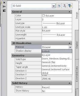
To the right I clip various dialogue boxes to hopefully show you the path. If you are new at this it can seem a bit daunting but most of this would be set up in your library files and you only need to tweak a colour here and there. You can see the render material has no colour assigned. You can also assign a % of colour and % of bitmap if that helps.
Also to mention that I go against the long winded approach to naming that is adopted in Adesk products. Of course this may be necessary for a hospital wing but you are going to bring your system to it's knees if you try to have so many RMats that you need to group them so catagorically. Unlike Max, ACA is also trying to do lots of other things than just concentrate on shapes and materials. So I use direct names.
Roof-Colourbond.
BrickFace (I should use WallBrickFace but that's too longwinded for me).
Also the shorter, the less scrolling you will have to do.
Grass etc
ah I could waffle on forever..... hope this helps you.
cheers
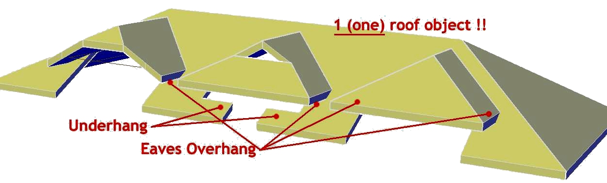
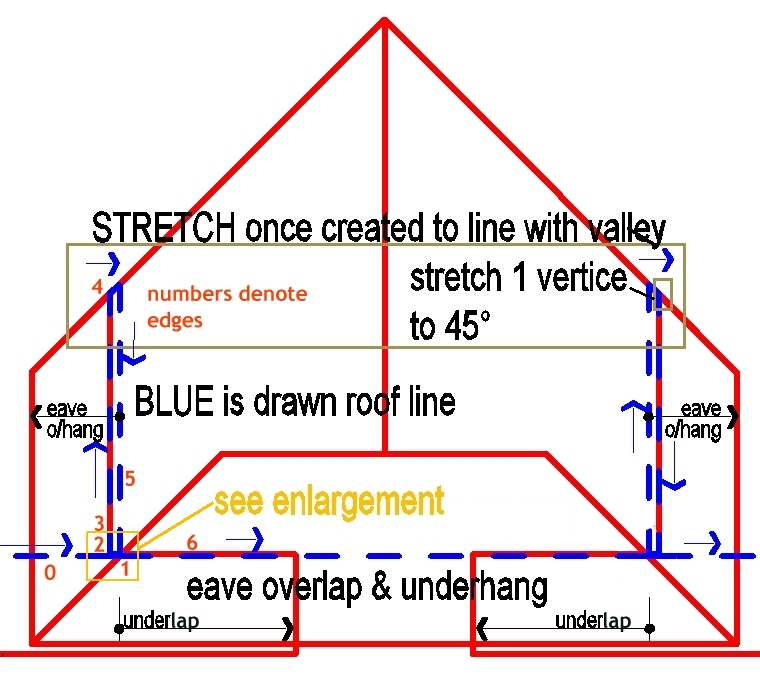


 Here is a closeup on how to get that overhang happening in another common situation. Here the secret is a simple gap where it overlaps. Again the blue line would be turned off and you are left with a clean roof shape. I would stretch the inside snapback blue line to the left once created to line up with the forward ridge. This will align the underhang with the main roof as you will see if you do it.