Sunday, March 20, 2011

Do you believe in ghosts?

Here's my ghost story!

This is something that I have had occur over the years from time to time.  ADT2005, 6, ACA2009 and 11.    I have strange issues occuring with walls mysteriously not cleaning up properly and strange interference from unseen (wall?) objects.  I've called them 'ghost walls' as they aren't there and won't show in any view or display rep even Diagnostic whiich should show something.  I believe they are 'deceased' walls having been killed (erased) but they just don't want to go!  Have they unfinished business? 

I've tried deleting everything from the drawing and the purging the styles using the sweep tool but some styles won't go!  Reading autolisp tutorials I've read that you can query the database for an object and see if it's erased and if it's still present in the dwg database even though erased.  I gather this is for the undo options where items deleted can still be restored if you undo your previous actions.  However I thought this was until you close the drawing and I would have assumed this information is lost forever.  Or so I thought.  Perhaps they don't want to go and come back to haunt my drawing.

What's interesting is that the purge styles function in the style manager (broom) would not purge lots of styles & objects and the purge function would not remove lots of empty layers.  It's like a complete breakdown in the functions.  Thinking I might learn some new useful information I went thru a copy and LAYDEL each layer. (I draw a line on that layer so I can select the layer).  This had the interesting effect of then allowing the Purge Styles to work and Purge on blocks as well??  At that point my Ghost walls had appeared to have 'gone to the light' and I no longer had my cleanup issues.  Some aecmaterial definitions hung on perhaps attached to the blocks still resisting.

I copied my square outlines from the picture file you see here and posted them back into the file I copied to use as a template thinking that they were going to coincide with the previous project walls but they didn't.  Not quite anyway.  Maybe this is a good reason to start from a clean template!

So I'm not sure what I learnt. Not about to delete all my layers from my functioning drawing though I suppose I could WB all the info out and then purge and then bring it all back in and see if that works the same. (I would loose the x-ref connections to the aecElevations).   I had just moved it all to the left away from the ghost walls and the issues go away.  I just can't draw in THAT space.  Hey it's haunted!                 So....

Do you believe in ghosts?

part 2
Well as it turns out, as I was showing my younger workmate my haunted drawing, he pointed out that my Isolate Objects globe was red!  After unisolating objects it turns out that on grabbing a previous drawing as a template, I had certain portions of the drawing hidden and brought it along into my new drawing.  So the hidden walls were causing the cleanup problems!  
Or were they?  After removing all the now unhidden but unwanted drawing portions I still had cleanup issues! Sometimes advances in technology just get too fancy! 

I wonder if this is the answer to the issue I've had over the years from time to time.

Wednesday, March 9, 2011

Structural objections !

James sent me a bunch of Structural Members he's been playing with that look great except they're not really structural members!  In the great spirit of not accepting a 'tool' for what it is but exploring what it could be James has used SM's to create excellent 2D detailing tools for those repetitive items.  In case you ask the obvious question "what about using the Detail Componant Manager" which is designed to do this, it's not set up with australian  details and there has been no Australian issue like the UK version.  We'd have to customise the database and then learn how to upgrade and maintain yet another Tool!  But yes you could use the DCM :-)


I've been tinkering with Dynamic Blocks to do much the same thing but there is a real advantage for an ACA'er using Structural Members.  The more you use a tool the better you are in applying it and SE's can be very handy in virtual construction.  For e.g. Structural members are great for creating a steel beam, adding end plates and the repeating cleats at set distances.  So essentially the tool can also be used for 2D work in the same way.  
The disadvantage is that blocks can't be rotated or mirrored so you basically have to create the block in the orientation you want to insert it.  However in the case of the roofing purlins in the example shown, the whole SM is simply rotated to the pitch so the purlin block would be inserted as though flat anyway.  Here's a bunch of wall styles SM's.  Constant materials like wall cladding are componants of the SM.  Periodical items like studs or hanging straps are added as blocks.
So you end with dynamic detailing componants that will stretch and add components automatically!  You do need to know when to create a separate style as in the window sill illustrated here.  It's attached to the window instead of the bricks.  Sometimes things get TOO complicated and besides, separate components gives you extra flexibility.


I hate fiddling with those repetitive sheet profiles.
James, having done much more commercial work is good with SM's.  Myself I still struggle to understand why I must create a pier base sideways to get it to insert properly.  But the more I use any of the tools and 'get' how they work I get increased productivity in knowing just how to use a tool, where to use it and when it won't do.  I can model most things very quickly now because I understand what tool to use and how to use it effectively.  Doing what James has done with SM's is going to teach you a lot about Structural Members


So I might as well share with you some of James' other  tricks.


I blogged an option for displaying Vertical profiles mainly for the purpose of rendering but James showed me a better way using a curtain wall, with only Profiled Mullions showing, in the shape of the sheeting. CWA's can have their roof or floor line edited-in-place for easy matching to a building shape and the profile follows suit.  The curtain wall might contain other componants but here it gives flexibility for the sheeting alone.  This is a good quick way of get vertical profiled sheeting into your model. Through components you could control different display for different display reps. ie. this for 3D, just hatching on another component for aecElevations.


Here is a wall style James developed for use in large commercial projects.  Adding components for sheeting, insulation, cladding and each expected purlin and then adding a sweep to each purlin component you get a detailed wall that will section, elevate and off course display well in plan.  Being a wall it will cleanup, has roof & floorline edit and the subsequent purlin components will appear as your height increases.  Higher wall this time?  Add (copy) some more purlin components in your wall style, add sweep and you're done.  If your wall is low, the higher purlins don't appear. 


Hope that helps stretch the paradigm a little for ya!


Friday, February 25, 2011

Drawing Properties

I described here how we use the drawing file custom properties for our 1 File for Multistorey to store the project data which is automatically grabbed by the title block and cover page.  Well an email to support (subscription is useful for something occassionally) turned up this link and an excellant autolisp file that can bring a preset list from a .cvs file right into the drawing custom properties ready for you to add the project data to.  (There are 2 lisp files posted at this link.  I used the first issue for .cvs files.  The 2nd amendment looks for .xls files but it didn't work for me).

Commands impdwp, expdwp and clrdwp import, export or delete (clear) drawing properties. Once you have them in your template they can just be updated for the next project but if you already have a project and want to bring the data in, here is an easy way to do it.

Been to Archidigm lately.  They have released a new ACA door style set and checking out his windows and the many display options to get detail quickly and efficiently is impressive. He has video's of his street kit in action.   And don't forget his intensive Development Guide.  Purchasing one of Odin's products get's you access to his classroom and there is a treasure trove of info available for your ACA obsessing delight.


Thursday, February 17, 2011

Doing it by the Book NOT

As a user since ADT3 for must be 6 or so years it's only in the last couple of years that I have hit an upper air stream in terms of productivity increase with ADT/ACA.  I feel that I have finally 'got' how it works and more importantly how to work it.  That includes not doing as I am told.  Well not always.  We all use this product for lots of different types of projects and the requirements of a hospital project have very different demands to a 2 or 3 storey residence or a back room extension.  The product is really developed with the hospital in mind but my work is mainly residential.

Here's some ways I have NOT done it by the book:
  • Development of a 1 file for multistorey approach using custom (simple) autolisp programming, custom layer standard.
  • Developing my own simpler Layer Key Standard with many less layers.
  • Practise that avoids dependance on the 'latest' interface such as using keyboard commands rather than point and "oh where is it this time?" click chase the ribbon.
  • Return to solids rather than MassElements for modelling certain one off library elements.
  • I've abandoned aecSlabs in favour of using aecSpaces.  They are so much more easily edited.  They don't have edge styles though but they do have componants and can be rendered.  I do still use slabs but not mostly.  Unfortunately spaces stretch oddly, if you 'grab' their centre point the whole space moves instead of stretching as the old area objects did.  
  • Getting to know the Roof Object intimately and understanding what it can do and not converting to the slow, less intelligent, cumbersome Roof Slabs.
  • Just knowing all the ways that won't work and the ones that will and knowing how far they will work so I don't have to fiddle.
So I thought I'd share some experiences that were successful and simple and worked.  They may or may not work for you in your situation but might be worth considering.

example 1
I don't use the Project Navigator for small projects and will build multilevel projects in the one file.  However one advantage of the PN is in regenerating elevations without getting unwanted elements added in (like text) and having any new modelling elements automatically being part of the selection set (when the file is saved and the X-ref is reloaded).  So on certain projects I may create a 2nd file to X-ref (overlay not attach) the model file into, set up the elevations including room elevations, sections etc and x-ref that back into the model file to complete the set of drawings.  The advantage is the 2nd file will have all the right layers turned off and on so only desired elements are captured in the elevation (like in the PN) and also once the x-ref is selected, any new elements added to the main file are automatically selected for the next refresh or regeneration of the aecElevation.  You can do all of them at once!  You can x-ref in the model several times, renaming each instance if you want to set it up in different layer configurations for different purposes.  A section or internal room/cabinet layout may require different layers than the elevations.  Changes to the model file need to be saved, and the x-ref's reloaded in the Elev file, saved and then may be reloaded back into the main file if that is where they are inserted onto a sheet.  Another advantage is the aec elevation/section objects are not in the main file in your way. When x-ref'ing the Elev file back into the main file, only the required objects are shown, the unwanted portions are x-clipped out. BTW 'overlaying' and not 'attach'ed means the x-ref will not travel with the file when x-ref'd to another file.  Here that would cause a circular reference and won't work.  If you organise the Elev drawing space as you want it, you only need to x-ref it back once into your main file for correct placement ready for the sheets (already set up in my tabs from the template drawing.  This means all the drawing sheets are in the one file.
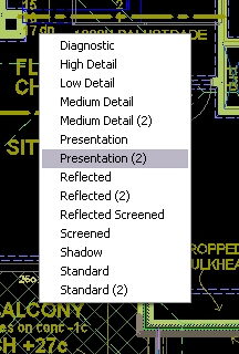
In the above 2nd file (Elev), layers are not really important, only where you need to sort items like in a floor plan that is displayed several times in different ways as a working floor plan, sketch plan, reflected ceiling plan, electrical plan, landscaping plan, site plan, roof plan, rafter plan, ceiling timber plan etc. so I often simplify the numbers of layers I use.  Using .stb plot style greatly helps this.   Having a seperate file does allow some multi-user access to the one project if you need that.

example 2
I recently modelled 4 single floor units in the one file (lets call it SITE drawing). That file was then x-ref'd into another file(s), clipped down to one unit (per file) and the full drawings for that unit produced in that file.  The benefit I found in this method was that altering an aec style updating all references as it was all in the same (Site) file.  (On larger projects you can use project standards but this is an extra process and is not on the fly).  As the complete model was in the main file, there is only one reference of the model and coordination was automatic.  I wanted this fine coordination as I was also using the file for rendering and exporting to 3DWF although that is a pretty dissappointing option at this point but I wanted to experiment with it and wanted to keep it all together.  Rather than a seperate file I like to keep the file always at a ready to be re-rendered at any point rather than having that as a seperate file.  This keeps all the documentation side out of my modelling file for rendering.   I am about to use this method on another project of 10 small single storey homes as it was quite efficient. 

Don't forget there are lots of ways to work on one area of your model (as opposed to having to split it up into x-ref's).  Using Layer Isolate or the the object isolate tools are good ways to get data out the way quickly.  Available on a right click is the Isolate Objects tools.  You can hide lots of components you don't want to see for a while even if their layer gets turned on.

Anyway, don't think that the method presented as THE way is always the best way.  Not that it's usually the wrong way!    Sometimes it's just the long way.

Cheers

Tuesday, February 15, 2011

Free Tree Downloads

If you are into rendering in any way you may have seen Xfrog.com which offers a tool for creating and editing trees and plants.  Well they have just released quite a portion of samples for you to try out.  Among the strange list of download options for max, maya and terragen you also have the old 3ds format for 3DStudio which I think is now a defunk product.  Using the 3dsin command, these tree files (oops see below) can be brought into AutoCAD for rendering.   Each zip folder downloaded contains a number of 3ds files along with bitmaps (tif) for leaves, bark etc to be applied to the tree. Whilst the tree is modeled, the leaves are a single face for a bitmap to be applied. 

There are some tricks to getting the 3ds file into AutoCAD though.  It seems it can't handle so much data (another memory handling problem?) and so you are best to load portions of the info at a time.  But oh dear in trying to test this thru my ACA2009 crashed each time trying to bring the file in. So I loaded 2011 which can save the files down to 2009 (for non ACA items) though I am wondering what the translation does to the material definitions.

FAIL again.  Crashed every time with xfrogs 3ds files?  I had loaded a couple earlier so perhaps I need to reboot.  I'll report the problem with xfrog and see if they offer any solution.

If you get past the crashes, and the load fails, try loading without leaves and roots. once imported, do it again and this time load the leaves (do you need the roots?).  I have a technique for simplifying the number of materials so I might not assign any material, using my own oft repeated material (e.g. Leaf1). In this case the leaves are just a square face and require the leaf bitmap to look somewhat realistic so I might include materials. I also don't allow multiple layers and put it all on layer 0.

Anyway, until I get it successfully loaded I can't post a picture of what you might expect.  If I do I will update this post with a sample pic but it's all there on xfrog's site.

er...happy rendering

Saturday, January 29, 2011

Multiple Levels in a single Drawing File? Part 4 (updated)

Thanks for the feedback on the Multi-Level in 1 file approach.  I know it's not for everyone.  Some of you don't like messing with layers.  That's never been a drawback for me - I have aliased the Layer commands (were from ExpressTools) to quick shortcuts and use them alot as I work and have found it very efficient to do so.  (I've now incorporated those shortcuts into my Levels autolisp so you will have them if you ask for it (& provide email)).  Makes it quick to manipulate between layer set groups, or singles whilst I am working on different parts of a drawing.  However my ML system is tied to a layer set and that may be a drawback for some.   Some have asked for (& received) a sample file (you need to give me your email address - I will NOT publish online).  Maybe a system such as this could be incorporated into the product somehow like the Renovation set but I wouldn't like to see it get complicated.  I like it simple.  Along with my understanding of the roof object this has made residential work SO much quicker.

I should say this is for advanced users.  Beginners might feel a little swamped.  Email me for a sample!  I'm really only explaining my theory here as to how I set it up.  Now...


Did I mention that I use a different wall cleanup group per floor?  Again easy to create.  Open Style Manager, Drag Standard down until a + symbol appears at the mouse, let go and another cleanup group, nicely named 'Standard (2)' for the 2nd floor appears.  If you use something other than Standard for your walls then just copy that. I only just discovered the 'drag and let go' routine.  Makes it so easy!!  I then manually change my upper floor walls over to the new group.  Haven't thought of a way to automate that yet nor explored fully how the change to the cleanup's for walls at different Z levels  (version 2009) has made but it all works fine with the seperate cleanup group.  (As I often will use a similar previous drawing as a template for the next job, I will often have an existing wall to 'As Selected' right click on and draw with so it already has the cleanup group set.  i.e. I've changed to Level 2, the old level 2 is there off to the right and I click on a typical wall, right click and choose 'As Selected'


Stairs An additional item I need to share with you which require their own special treatment. My thoughts for handling stairs were along the idea of a spanning construct used with the Project Navigator but of course I can't bring stairs in at a different level.  Many have used 2 different stairs but I didn't want such a work-around.  I just wanted it to work and it again turned out to be easy to accomplish but you need to do a little work again in the Display Manager.  So here it is.   
By diving into the DM 'Sets' (see image) and adding a 2nd 'Set', copied of the 1st such as 'Plan', dragging 'Plan' so the mouse shows a '+' symbol and dropping I get a 'Plan (2)' set.  Perfect!  I can do this for however many different display styles I want for the stair utilising the OOTB ones preferably.  So Plan, Plan Presentation,  Reflected, etc.   If you want you can simplify and use the same 'Plan' display for all your different display's whether it be working plan or a reflected ceiling plan.

Now moving down to Representation by Object, scrolling down to 'Stair' and we do the same thing to add another display representation set but this is only going to apply to the stair.  Again this is done to the OOTB template and is quite easy to do, however most times I grab a similar project as a template and it's already set up.  Differently as done for the display representation 'Configuration', I am going to do a little more than just alter the cutplane however don't panic!  It's not complex.   So here we go.  


Selecting an existing display I want to copy for a 2nd floor and dragging down it becomes a new one with a (2) appended.  Ideal!!  Now we just need to scroll across and associate the (2) with the Display 'Set' (2) and unassociate the original with the (2) set.  Ok your way out and then draw a stair in a (Presentation) display.  Editing the style you should only see one set to alter (it's the bolded one). (2) should not be bold.  Now change your display set to a (2) and again edit the stair style.  If you made your changes correctly, you should be now editing a newly created display rep for the stair for the 2nd floor and whatever changes you make will only appear for the 2nd floor.  Now this makes it easy to set up a stair for ground floor showing the stairs going up and for the 2nd floor display with the stair going down!  Or however you like it to show!!  The final display changes can be done in the environment you are familiar with through working the style from the stair itself.  See these 2 images.


Viewports (update) will need to be adjusted for each level displayed. It's seems that if you have not changed a viewports display rep then it will be whatever your current model space is set to.  However if you specifically change the display rep inside a viewport, it will stay that way and not automatically alter (no idea what variable that is).  So if you are setting up a viewport for your 2nd floor, double click inside the viewport and change the setting to Medium Detail(2) or whichever you need. Then also change the Elevation setting and you are done.  If I use a previous job as my template these are already set though the 2nd floor level may be a little differerent height and may need to be altered.  - easy!

Stairs another way (PN & X-ref's).(update)

                                      James doesn't like manipulating layers and would like a 1 file system without having to manipulate layers.  He sent me a file showing a stair that displayed differently in response to it's elevation.  By setting the stair elevation to minus -2900 in the properties pallete, (as you would in an x-ref system for the 2nd floor plan) his stair changed to the 2nd floor display much as I show above but using the same display representation   He achieved this by altering the global  'Display Below Range' to   -2900 (normally set to -300) for that display rep.   Of course this requires the stair set at 2 different positions and doesn't work for a one file system, but may be of interest to those using X-ref's or the PN.  Interesting indeed but I haven't worked out all the ramifications.

Spanning Walls
If you have got a file from me and it has Plan Presentation (2) in the Display Manager under Representation by Object  - Walls, then it's not required except where I was trying for a spanning wall which needed, like the stair, to be able to be viewed differently from the 2nd level.  This would require a style over-ride for a style only used for spanning, or an object override.  I'll have to discuss this in another blog but you don't need this except if you are trying to avoid horizontal lines between same plane upper & lower walls in your elevations. Since I often use alive elevations (the model viewed from different sides with hidden lines) for sketch presentations I've tried to use this option.   I'm not sure it's successful but Watch this space !

Tuesday, January 25, 2011

Mult-Levels in 1 File?

Great to have some interest in this idea.  I've sent out files to some. If you haven't given me your email address I can't email you anything OR reply to you!! As you can see no one's email has been published so be confident I will protect your privacy.  I delete your comment rather than post it.   If you've tried to follow my online notes, it may be difficult and I may have missed things (hopefully not).  It's hard to anticipate everything about someone else's setup. 
 If I send you a file you can compare and see how it actually works (and it does) and, if it suits you, use my file for your template.  Feedback is welcome too.  
My intention is community as I like the open source idea.

This 2nd image is 3 storey for which I had to add another 'level' of commands for.

I'm presently working on a split level house which presents more challenges, some which should be simple to resolve and some are resolved because the typical wall style has it's cut plane over-ridden. I'm adding some extra commands to change the Z plane level without changing the Level you are working on so you can have different levels for the same 'Level'.  A 'Level' would correspond to those collection of levels you want viewed in the same plan view.
If you have specific queries feel free to post a comment but it's best I can send you a file to try it out.  If you are using ACA2011, I am sorry but it has BIG problems that will hopefully be addressed but it does significantly negate partially the reasons for Multi-Level in 1 File (rendering & memory issues).  I may post my totally negative blog review on using ACA2011. For the record my great increase in productivity is in using ACA2009.
And also I say again.  I promote this system for residential and small commercial work. Larger projects should really be done with the project navigator or at least X-ref's but I will be intereted to see how large I can get.  As computers increase in capacity, the size of file you can handle increases.
I keep intending to put some tut's on Youtube on the roof object, rendering and materials and this idea.  Now that I've published it I have to do it hey!  So much simpler to watch instead of just read.

cheers

Saturday, January 8, 2011

Windows & cutplanes

David Koch - The Architects Desktop, has two excellant posts on getting windows above the cutplane to display, something I've always blundered through but his explanations makes it very simple to achieve at least my desired solution .
 
Displaying Windows above cutplane  and
ACA Wall settings at openings. (ok this one is not so simple to understand).

And whilst visiting here, David has a link to ACA / ADT scheduling resources that is very valuable.  He's captured wisdom from some great minds including his own and put them in one place. I can use schedules because of what I learnt from here.

David has help Paul Aubin with his latest update to the 'Mastering  ACA' series of books now called
The Aubin Academy Master Series: AutoCAD Architecture 2011

As Paul tells it, the bulk of the work for ACA has been done by David this time around and my thanks to David for all his efforts on continuing the education for ACA..

I've said before that I learnt how to use the Project Navigator after reading Paul's ADT2004 series and I dived in on a complex project on ADT2005 and was pleasantly surprised how it all came together so well.  Paul himself has some good movies to watch over at Autodesk Exchange, also a great resource.  So recommend Paul's work.

Hope the new year's looking good for you!

Cheers


Wednesday, December 22, 2010

and Now for the Really Important Stuff

Well we're off to a wonderful holiday destination for just a short break.  I think we have the blue trailer and some storage space in the red sea container reserved.  I sure do need the open air exercise and I'm assured the pool is clean.

Thanks for sharing the journey.  I hope you all are holding your own as the world shudders. 


I've been working from home looking after my kids on their aussie break and they have got into Sketchup - release 8 just released.  My middle son has designed his dream house.  Not sure about the engineering issues but it's gets a great view and will catch any breeze!  They have also messed with Envisioneer Express (free).  So if you got young'uns who you'd like to inspire but don't want them messing up your cui or your pallete then these are great simple and free options for play. 

Actually I tried out Sketchup myself to be able to quickly review the sun path for a new display home I'm working on.  It allowed me to quickly test the height and angle of a highlight window design. The sun slider is quick to show real time shadow and I was able to determine refinements required to allow in more winter sun and still block summer sun. I reduced the overhang.   I could also evaluate the effectiveness of solar panel positioning and as here determined that some panels were just not going to be very effective and need another location.

To get your aca model into Sketchup use the 3DSOUT command on a 3d view. (Don't have 3DSOUT??)  You can then import the 3dstudio format file into Sketchup.

I also placed a camera and rendered shots at different times of the day using ACA, easy to adjust the time and rerender but it's not real time.  Just looks better! 
I am working on a 3 level house now and upgraded my lisp tools to work on it within 1 drawing and it's working quite well.  I have another post to share some finer details of my system of working in one file.  I've also added some extra commands that allow more quick efficient manipulation of parts of the building model.

anyway.....

So here's to you and yours.  May you have a most enjoyable Christmas holiday with good family and friends, may your ability to shoulder the troubles increase and your understanding of the deeper things bring you peace.  May your laughter be louder and longer and your tears be shed in joy and in sorrrow with those you love.

In this, His season,
God's best to ya
Cheers from AusACA

Saturday, November 6, 2010

Multiple Levels in a single Drawing File? Part 3

Ok to continue my crazy idea of completing a multi storey building in one file in ACA.
Here's a sample drawing with all layers turned on (not any different to look at from X-ref'd level files) and the rendering (incidently done in a seperate file after the CD's were completed because I couldn't resist.  Design by others.


The Cutplane & Display Configurations
The cutplane determines at what height a horizontal cut is made through your building to show a plan view.  You can adjust the height to cut through the windows or as the default 'Reflected' display rep does, raised it to miss windows & doors altogether. (I lower this to cut frames as I display them in the electrical layouts for residential work).  Now I override the global cutplane for walls and this is discussed here.  This means that whatever height a wall baseline is, it will display normally and not disappear because it's above the Global cutplane.  So this will mean that you will need to rely on other methods to not display some items (walls) that are not in the current level but this is okay because some items ignore the cutplane and don't work like walls anyway.  Here is where I use layers and my first designation in the layer name of it's level (1,2,3, Site etc).  So in issuing a L2 command to flip to the 2nd level I need to adjust the cutplane and I do this by creating another Display Rep.  This is a very simple procedure.  Opening your display manager and noting what Configuration is current (in Bold text). Select and right click and copy and then paste.  This creates the same DR with a (2) attached - sweet just want we want!  Actually that's the long way to do it.  Try Selecting Standard and whilst holding it, drag down and your mouse should display a plus.  Let go and the **(2) file is created.  ('Configurations' are the names that appear in the selection box RHS bottom of your drawing screen).

Now I move to the CutPlane tab and add the lower floor to current floor height to bring the cutplane to the same height for the 2nd floor.  Ok out and test in your display Configuration selection box that you now have a new config to select ready for your second floor. 

You can create these extra configs for any of the DR's that you use.  I would generally only create 3 extra for a 2 storey home and no other fiddling is necessary but you may need more depending on the type of documentation required.


Z Plane and the Elevation
Of course when you draw a wall you need to be able to restrict the baseline to the current level and not snap to some line lower down.  The OsnapZ variable does this for you and the button is to the right of the Elevation setting.  My lisp reads the 2nd floor height you set via a 'SetFL2' command and wrtes it to the Elevation setting and then locks the current Z plane to that height (sets OsnapZ to 1) and you can be confident that the any snapping will ignore the Z height.  Issueing L1 will return back to the ground floor Z plane and elevation height.


Controlling Display
So how do we flip from Ground Floor to Upper Floor to Ground Floor Electrical to roof plan?
Actually I don't use a roof plan but I could.  Simply by using lisp to automatically execute the -Layer command and using wildcards to turn layers off and on I can instantly switch between various groups of layers.  L21 will switch to the 2nd floor but show the underlying walls of Level 1 locked so they can't be moved.  L1E would show the Ground Floor but without text and dimensions and also show the electrical layout not shown for normal Ground Floor plan.   Basically by following conventions and grouping rules with my layer names I can create simple lisp routines to get whatever display I need.  As yet I don't control the Display Configuration via lisp completely and on issuing a level change command, the dropdown list will popup allowing you to cancel (if the current one is acceptable) or select the new display rep to change to.  I know the tools to change are there but I need to step up my lisp learning to get the job done.

So that's it.  Relatively simple for something I desired for years to accomplish and now am using successfully in production with significant productivity increase and ease of use with some simple Autolisp.  As I said at the start, I am disappointed that this wasn't presented as an option now that I know how simple it is to implement.  I am happy to send you a sample file and a copy of my ever evolving lisp file to check out so drop me a comment with you email (will NOT be published) and I can do that.  I hope I have presented this in a way that doesn't scare you off.  Drop back and check out the reasons why this is such a good idea for smaller projects if I haven't yet convinced you.  See here if you missed parts 1 & 2 for all the MultiLevel posts..

Next I need to share just a little more work on stair so you can use a single stair and see it differently on the ground floor plan and the upper floor plan.  Odin Cary discussed this problem years ago here and I did use something of his logic (developed for the PN) to use in my system.


cheers

Saturday, September 18, 2010

Rendering is fun!

This is another project that I keep rendering over again.  I have strict council guidelines to match a pocket of pre-war housing and I have to ensure that I satisfy the gods... er I mean the planners. A pretty picture can go a long way in getting support.  I am not supposed to have a garage door and possibly the brick beam is going to get vetted but I'm hopeful they both have a chance. 


Being able to constantly refine a design, hit render and in around 5-15mins (dependant on settings) I can have a reasonable image to sell the design.  It goes a long way to winning a client.  I will use the actual model, viewed from each side in a viewport with the vp set to hidden for elevations and they aren't perfect but it's quick.  We can use aecElevations down the track when we get serious but time spent rendering will win over everytime.  The included expanded (around 100) RPC's are enough to get you by though you can buy extra as you need it.  To get the RPC's going you will need to download from Archivision.  Look in your browser.  I've mentioned before that if you have a license of 10, you can use the extra RPC's included in 10 in 09 without any problems.

Jay of Visionrez has posted some helpful tips on getting started in rendering in pdf form for you to download.  He explains that it was created for their VR clients but it's mostly useful for anyone using ACA or even Acad.  (Can someone tell me where this is posted?)

Some simple tricks n tools shown in this image.
Rafter ends are a block of the rafter overhang ensconsed in a curtainwall style which automates the repeatable spacing. (I'm still figuring out how to automate the hip rafter).
The front fence is a railing style.
A curtainwall fashioned as vertical blinds create an interesting look behind the windows.
The boarding to upstairs clad walls are a profile applied to a cladding componant.
Roof hips and Gable treatments are profiles (shapes) applied to a structural brace style.
Gutter is a wall style with a profile.  (my typical fascia and eave lining is turned off).
Windows have a surround attached to fatten them up.

Having these items set up ready in a library and in a pallete at your fingertips makes bringing together an image like this an efficient process.

Rendering  .. . .. . you gotta try it.

Sunday, September 12, 2010

Model Rendering (edited at bottom)

James posted some lovely images in the ADesk NG and I thought I'd like to add it to my blog as well as my wallpaper.  This is modeled and rendered inside ACA2009 and shows that it's quite capable of a decent image for presentation.  
One of the tasks for the image is as part of the presentation to the local authority to gain their support for a project that overreaches in some aspects of planning regulations.
A particular nicety in this image is the shade ribbon (a ribbon I like) that meanders around the balconies and brings about a wonderful interplay between the regular rhythm of the balastrade both glass inside the ribbon and solid outside, and the random travel of this shade device.

James has drawn 2 circles, one offset of the other, extruded both and then subtracted the inside from the outer resulting in a tube.  A plan view PLine was also used to map out other flat sections, extruded to a solid, other solids used to subtract portions and after some union'ing the whole lot was converted into Mass Elements. 

I've just derided the overuse of ME's in my last blog but here they are quite useful because as James points out, they obey the cut plane when displaying each floor.  Now He doesn't use the PN but regardless, positioned correctly, the ME ribbons will 'cut' correctly in the plan views whereas using solids would not, having no intelligence of that sort.  Also in this situation the ME 'Ribbon' style can be assigned an aecMaterial and different rendering options can be swapped quickly to explore ideas.  With an ME style, you only need to deal with the aecMaterial and mess with the 'Render' material to do this.  If you used solids here, you would either have to alter the actual render material used (loosing previous options) or create a new material and then remap it to each seperate portion of Ribbon each change.  The style system of ACA works well here although masselements are now more primative than solids and not able to show a true curve being segmented.  But if your settings are high enough (as here) this can be barely noticable.

Oh and James is working on a 64bit system with 8Mb of RAM.  I doubt I could finish such a render on my 32bit home system with only 2Mb of RAM.

tips: remember that ME's can be easily turned into solids and visa versa.  Select the object and RC for options.

I should mention that the first image is an updated rendering. BACKGROUND command will allow you to choose options such as a background image (sky)  seen above, or sun & sky with illumination (no background) seen right.   If you want to place a sky picture in later you can use a solid colour which makes selection easier in a paint program like photoshop or free GIMP.  The Background setting can be saved in a VIEW you create. If you added a camera you will already have a view by the same name as the camera.  Using a camera can allow easier adjustment of the view and easier setup in plan view.  I'm still playing with these settings and cannot get light shadows with a sky background as James managed to get in the top image here so I've gone to pasting skies in later in GIMP.  I'll post some images later to illustrate more on these settings.
James' Tip:  If you are not using sky illumination you may have trouble getting shadows looking anything but dark.  Try GI (Global Illumination) and forcing FG (Final Gather) on (not auto)  (more the FG than the GI).   "It's the only way of achieving lighter shadows if you don't want the generic mental ray background (Sun & Sky setting). I also use the logarithmic exposure control over the automatic."   You can see the Globe button lit up for GI to tell you it's on as the settings display whether it's on or off (no greying out functionality here).  The interface design is rather poor on a number of the palletes in 2009 and I don't think it's really improved in 2011.  Be aware too that these two settings will greatly increase your render times.  For my day to day images I will not use them but if I am trying to render higher resolution and better quality for special shots I will turn them on, set the render to go when I turn the lights out and hopefully in the morning I am greeted with a fabulous image.                                                                                                                          If you are using RPC content then you may be warned to alter your Physical Scale setting.  Be good if the defaults were set already.  James thinks it's 1100.  I thought I read 600.    Oh!   this pallet is raised by the command RPref  .   Sunproperties will open the sun pallete (I've alised it to Sun).
Other settings I know to mess with: If you have lots of RAM, you can try setting your memory limit higher than the default 1048.  With 3.5Gb I have used 1800 but 2000 will crash.  My home system with 2Gb will not get above 1600 (if I am lucky to get that).  If you can get to 64bit and lots more RAM you will have better success trying to render larger images.    At the top you can select from the presets.  Medium will give you a reasonable quick render (5-20mins) but High or presentation turn on FG & GI and alter some of the other settings so only use them when you are ready for the final render.  Of course the render time is greatly effected by what you are rendering, the materials applied, transparency, reflectively and the settings you have applied.  When experimenting don't work on that 18 storey building!  Try something small, even a few masselement boxes on a floor so you can get quick feedback. 

Rendering is fun!!  Go on.  Have a go