Wednesday, February 18, 2009

aecRoof Object - Part 4

Now I am talking mainly residential roof's here but I don't discount the commerical roof, with many commercial buildings built using residential practise. You may need to refer to the earlier parts of this series 1, 2 & 3.

The simple Cutout for the roof object is just a matter of tracing the outline of your roof and editing the edges (right click option) of the cut out portion and changing the overhang and the slope to 90. Just remember if you miss a point (vertex), you have to recreate the whole roof!

What about the Cutback eave? I showed this in my wall example, having to edit my external cavity wall to cater for a cut back eave. This happens not infrequently here in West Aus. So how do we wrestle the roof object into cutting back the eave and showing the eave in one straight section. You would assume that you should have two end points and a point (vertices) for where the roof eave changes from overhang to none but you will be wrong. The Roof object can't do it and your eave goes strange. You need to have an extra point and the extra edge has to have 90 degree slope. That's illogical to the roof shape but it works. Once constructed you need to drag your points very close together so that the raking portion of the eave appears at right angles to the roof pitching line for a spandrel to end the eave overhang.

What about different plate heights? Can the Roof Object handle this? Very easily!
Construct your roof at your main height. Select your roof, right click and select 'Edit Edges'.Select the edges you want to raise and enter the new pitching height. You are done.
But remember that the roof object can't overlap itself UPDATE - WRONG so for e.g. the eave can't overlap the lower roof portion. So how can you do that? Resort to slabs? Chicken! Here's a method that takes just a little planning.  WHILST this technique works, being able to overhang itself is probably a better option as the valleys will self heal at the right height without you have to input.

Create the main roof and trace around the valley connecting the main roof to the raised portion. These connecting edges will get a 0 overhang and a 90 slope. Now create a second roof to position into the breach and you are done. Your new roof can now overlap the main roof and there are no unwanted lines on your drawing.

Tip: As I've pointed out before, don't worry about getting this cutout right for your design development stage. Just overlap roof objects as required to get your outer shape as you need. Once the design is final you can plan & trace and replace so your sections will look correct too.

Well that's probably as many tricks as I know to using the aecRoof Object without resorting to slabs. UPDATE - LOL Hopefully I've helped you to be able to use it more extensively, at least in the design process and be able to get it to look how you want.

Oh and I have added some more detail for a Dutch Gable and some interesting tips for gable infil and about the behaviour of the aecRoof object as a barge to Part 2 of this series. It's in the centre of the post if you don't want to read it all again.

Happy Roofing!

Monday, February 16, 2009

I've developed a Lisp !

It'th True! I'm slowly (very) developing a lisp. I have finally dived in and started to learn AutoLisp and enjoying learning my first programing language. Ok I did type in a random dice program in basic but that shouldn't count. And yes even VBA has been pushed aside in Autocad 2010 but Autolisp should be here for years to come. I've been trying to reconstruct a useful program that allows you to pick 2 corners of a room and it prints the size in metres in the centre of the room. Great for marketing plans. Turned a functioning program into one that simply delivers "nil". Some work to do!

AUGI is a great resource for learning lisp and has a newsgroup and some great tutorials you can download. Of course there is Adesk's own newsgrops.

I also plan to get my thick head around OpenDCL, an open source version of the programming of the dialogue boxes that you use.

My long term goals in case anyone (anyone?) is interested.

1. Program to facilitate levels within one drawing. Should be fairly simple. Manipulate layers, elevation and display rep. Need to automate text & dims to the appropriate level as well. Got most of it sorted in my head and manually tested and satisfied with outcomes.

2. Program to enable one touch to shuffle a multi-building drawing (either blocks or x-ref's) to a level assigned in a tag and toggle back to 0 elevation. Multiple unit developments on a hill side can't display plan view and create elevations at the same time if cut plane no longer intersects houses at different levels.

Let me know if you are interested, could help me, want to laugh at me or have any comments that could help.

(setq salute "best to ya")
(princ salute)

Saturday, February 14, 2009

aecRoof Object - Part 3

Here's a pic showing the roof object creating a number of different roof shapes. You may need to read at least part 2 to get what I am showing here and how to get there but in part 1 I am promoting the Roof Object as a usable tool even for construction drawings!
The round (2 pitch) roof was based on a 16 side polygon and how they usually construct it anyway though usually 8 sides. The flat top (name?) was created using 2 pitches and then adding a third 0 slope roof as similar to what I describe here. The Pizza hut roof is done using the double slope roof (check the properties pallete) as can the Mansard roof if the pitching is on all 4 sides (not 2 like I've shown).
The Dormer is simply another roof (object) sat above the main roof. The trick here is to create a 5 side roof shape, with the back planted end having 2 (triangular) sides with no overhang and the slope set to 90. UPDATE - see technique for dormer roofs and other holes. The roof object cannot have holes so yes there will be roof in the middle of dormer and won't work for sections thru' here. For a schematic section you could use a masking object or simply edit the section and delete the lines. That may even possibly get you thru' a construction drawing as well.

The floating or planted Gable is again another simple roof object with 5 sides. The trick here is the 2 sides with slope are too small to be seen so it appears to be a triangle. The VisionRez roof can do this slope without a length being required which is very smo

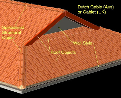
The Gablet or Dutch Gable (Gablet-uk) along with the Mansard, Half Hip and derivatives can be created using the technique describe in part 2. via editing edges.
The Skillion roof is the most simple but not obvious with the roof object. It would appear to be native to a slab. But aecSlabs behave differently (displayReps) and so I will use the RO instead.
Trick is to create a 90 slope roof to start with and only add a slope to the one side edge.
It can also turn corners and wrap around a house, even completely around. To get a verandah roof all around a house (with a hole in the middle for the house) create one roof up to the hip and then another to complete. Connecting at the hip end will disguise the use of two objects and there will be no unwanted lines in plan, elevation & model. (UPDATE: If you create a full square roof and add a second pitch at 0 to one edge at a height between the pitch line and ridge, you will get a hole. This is demonstrated in my file posted at AUGI and Adesk NG.

Hopefully you can see that the roof object has some versitility. You may well need to revert to slabs to do a complex roof but the RO can certainly go further than what may be immediately obvious. I seriously believe that with a little tweaking by the Autodesk team, the roof object could be a great tool for residential roof's. As it is - it's almost there! I don't care for edge styles as I am happy using a wall style for that
But it does need ;
  1. Ability to add/remove vertices (critical) UPDATE - it's there but hidden.
  2. Ability to cut holes (ok not so critical) UPDATE - reasonable workaround.
  3. Styles (ok not so critical but would be nice)
Now that slabs have componants, it may be required in your project and overtake the roof object's usefulness. But again think about how much detail you need and remember that the more complex the model in 3D, the harder it gets to manipulate it and the longer regenerations etc take. Sometimes you just don't need the extra data and can add info to a section (the only place it's required) just as easily.

Next I want to look at when a roof needs to overlap itself and the simple cut out section.

Wednesday, February 11, 2009

ACA v2010 and roof shapes

Are you searching for blog announcements on the latest version of AutoCAD and ACA?
I have been and there appears to be some exciting things happening in AutoCAD. How they translate across to ACA and how (and if) they are incorporated in the aec tools is to be seen. 'Mesh to solid' could be exciting! Could bring some serious tools to create site development work in 3D which has been sadly lacking. I shouldn't imagine I will do much organic modelling in affordable housing but when that housing is on the side of a hill then it could be useful.
One blog to watch is Shaan Hurley's Between the lines (the inside story).
Shaan mentions improvements to walls (good), stairs(gooder) and structural members (which have lots of other uses). The PN & interface have been touched, the interface probably just phase II of the ribbon (eugh!). The PN - not that I use it but for larger projects it's a great organiser so it will be good to see upgrades to it's shortcomings (phasing, options, timing, multiple buildings). No mention of roof's (sigh!!).

Gambril or Gambrel? Googling it I can see that the name is probably incorrect according to world usage. Americans don't use them (the aussie version) and I don't see examples elsewhere but we use them alot here. So if anyone has a correct name for this type of roof please let me know so I don't continue to show my ignorance online to the world. Or should I just call it a floating gable. That one kinda sounds like it should not touch the main ridge though.

UPDATE:
ok I should have googled it. Wikipedia confirms that my roof shape is known as a 'Dutch Gable' in Aus and a 'Gablet' in the UK. Americans call something else a dutch gable (one of those elaborate rendered gables you see on the hacienda in the old wild west movies). The Gambril or Gambrel roof also known as a Mansard roof is essentially a dual pitched roof. My friend Stuart comments "The roof you illustrate I know as a gablet roof which had its origins over here in roofs prior to around 1500 when chimneys started to appear. Earlier houses would be open to the roof with no upper floor and the fire would be on the ground probably in a central position with the smoke rising up to the exposed rafters and they would form a small gable at the top of the hip which would be left open (no gable wall) to allow the smoke to escape." Well we use them alot here in Oz.

Well now I'm better edjamakated!

Cheers.

Monday, December 15, 2008

aecRoof Object - Part 2

(Hint : If you have trouble seeing my pics - you can right click on them and select "Open in other tab" and it should open as a larger image).

I'm not going to repeat the basics that are found in the AutoCAD help or the tutorials. I want to focus on the extra tips for use here in Oz (and anywhere else :-) Here I am going to focus on creating a Gablet (dutch Gable to some) (Gablet-UK) plus a couple of other tips including adding infill, the barge board and dealing with the overhang (underhang?). The methods here can be used for creating other roof shapes such as a Dutch Gable.. Roof types with 2 constant slopes like the 'Pizza Hut' roof or the 'Mansard' (or American dutch gable,) the flat top roof with a skirt around are better created using the 'Double Slope' option in the Properties Pallete.
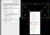
Create your rectangular roof with a hip end. Select the roof object & right click. Choose 'Properties' and on the tool pallete select 'Edges/Faces'.
(Note: This dialogue box shows the roof object tool's incomplete nature in several ways.) If you want to change the whole roof pitch DON'T do it here. You can only change one at a time.
Do it on the properties pallete under 'Slope'. You can however change overhangs 'en masse' by selecting one, several or all of the edges using Windows standard Control or Shift key options.
Now the lower panel shows a slope per selected edge and if you select multiple edges the lower panel greys out. Let's cancel out and get back another way so we know which edge we are editing.
Hint : If you can't change the slope in the properties pallete then it's possibly because you have edited an edge and added an additional individual slope so make your broad changes first before editing edges.
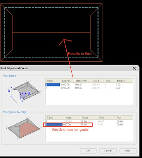
Cancel out and again select the roof again. Right click and select 'Edit Edges' and choose the right & left edges. Where-as before the dialogue box showed you all 4 edges, you now only have the 2 edges you selected. Select the first edge in the top panel and then click below the last entry in the 2nd panel under the 'Face' column. You have now added a 2nd plane for this edge. It will have the same slope as the main roof. Click in the slope column for this 2nd face and change the slope to 90 (vertical gable face). Now in the height column enter the height from the pitching (not eave) edge back to the face of the gable. I find this hit & miss but I get it eventually. (I'm sure you could do it mathematically.) Your height may be above the ridge so your gable may not show up. Adjust the height until it does. You now have your 'Dutch gable'. A reverse Dutch Gable can also be created by reversing the slopes for the 1st & 2nd slopes. i.e. A gable chopped short with a hip over.

Here is the dutch gable, used in the post war homes around here and every now and again copied today, but not often. Very easy to set up. Here I've easily adapted a curtain wall to act as my gable infill as the battens suit the repeated spacing. I had to give the CWA a tiny height and lower the baseline below the roof pitching line so I could right click and 'Roof Line /..." edit roof line and project into the shape of the gable roof.. The green barge on both sides of the gable is the SAME roof object. Adding a 2nd 0 slope at the same height as the main reverse dutch gable made the barge top section disappear where the gutter is. If I repeat this 0 slope on the other side the barge appears flat across this section. Interesting! Nice to have an object work with you but it's taken me years to learn these tricks to use.
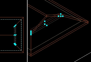

Now gables look better with an overhang so how do you do that (remember: The OOTB roof object will not overlap itself). Here's my best work around. Create a small section of roof (object) with slope to one edge and 90 slope to the other three. Position and shape it as the roof section that is overhung. i.e. the 2 side edges at 45d to align with the hips. In an 'isoview', align the new section to the existing roof. Make sure your roofs 'Edge Cut' are set to plumb (properties pallette).
The only drawback to this solution is a line on your aecElevations from the model but it's minor and you could pretend it's the flashing line for the gable wall over the roof sheet below.

Tip: If you have hatching to your roof material, setting the material hatching orientation to global will ensure the hatching to both objects align for your elevaiton.
Tip: Generally I position (in iso view) a wall style at the back bottom edge of this item, give it a very small wall height (10mm) and project the wall into the main roof object to create my gable infill. This peculiar wall style might have a frame & cladding componant so that I can apply a profile for the cladding. Note: If your gable wall is too high it will fail to project being taller that the lowest portion of the roof. It must be all below it (hence the 10mm height & bottom edge).


What about the Barge?
Gutter & fascia are taken care of by my wall style. But what about the gable end barges? I use another roof object! Draw a roof 50mm wide, set slope as per main roof and edit back & front edge slopes to 90 degrees. Ensure your roofs 'Edge Cut' are set to plumb (tool pallette – wish that was default!). Many use structural members and they have their strengths (getting quantities) but if you don't need Q's then the roof object is easier to adjust quickly because it maintains it's slope when the overall size is adjusted to suit different width. (It would be great if you had the edge option of 'Flat' along with 'Square' and 'Plumb' but as this is only for 3D and the unwanted portion of the barge dissappears into the roof then I am unconcerned ). Set your barge material on the first one (remember – no styles) and then copy around, adjusting as necessary. Remember to adjust the width in plan view and place using snaps in an 'isoview'. As the slope is set in the roof object it will keep that slope as you adjust the width - which is why I use them rather than a structural object. Update: You can use this option but I now use a structural object to get more detail for rendering.

Tip: Once you have built this 'circus', you can use an object anchor to tie it all together.
aecobjectanchorattach (alias to AOA or something simple).
Object anchors are cool but they can cause unexpected behaviour in connected objects so keep an eye on them.
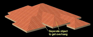
To get around the aecRoof Object's limitation WRONG of not being able to overhang itself UPDATE you can split the roof as I've done here. This takes a little planning but I've simply traced the main roof around the valley connection to the raised roof and given those valley edges a 90 (vertical) slope. Because the raised portion is a seperate roof object it can overlap as required.

Tip: When in the initial design phase, don't worry about untidy roof's if you have several roof objects overlapping. They won't show on your model or elevations as they will be inside the roof. That way, rather than convert to slabs, you can review the overall roof and perhaps replace it with one or more aecRoof Objects when the time comes to do documentation.

Verandah's?
Again I prefer to use a roof object. Like the gable overhang infill trick above, just isolate the slope to 1 edge and you can wrap around a main roof (wall). Of course without the ability to add vertices, make one mistake and you have to do it all over again. WRONG!
Tip: Create the roof with a 90 slope then edit the edges you need to slope. You will be editing less edges.
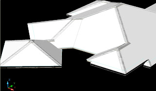
Roof hips for metal roof's Update: You can use this option but I now use a structural object to get more detail for rendering.
Here again I've found the Roof Object to be simple and versitile. Only necessary if you render or like your elevations to look complete rather than basic. Not having styles is a drawback but if you make the first one the correct setup and copy it around it's okay. These can be tricky and are fragile. You have two bottom edges with the roof slope on a 6 sided object. The other edges are 90 slope (vertical). Make the thickness around 5 to 10mm and sit on your main roof. Make the ridges thicker and they will sit above the hips like they do in real life. Ok I've also added a 50mm round structural object to get roller ridge capping which costs more but is much better looking.

There are a couple more small tricks to using the roof object successfully and I will try to be prompt in providing those secrets shortly.
Now why would you do all this and not switch to slabs? Well I'm just showing you the options 'is all'. Simpler roofs don't need the slab and it's easier to manage one object (KISS). The hips stay aligned to one another.  Be free to continue using slabs if you have them mastered and are happy with them. If you want to stretch an edge and want to see the rest of the roof adjust automatically though, you may want to revisit the roof object.

Best to ya (Now when did I really post this one? :-)

Saturday, November 15, 2008

aecRoof Object - Part 1

Can this tool be used for anything more than sketching? It's promoted as just a preliminary tool to map out the basic shape but I use it all the time right thru to CD's. Most of the roof's I do are reasonably simple and you may need to convert to slabs for complex situations but don't count out the simple roof object from being able to do the job. You can't cut a hole out for a dormer (update-Option) or chimney (can't remember when I needed to), it can't overlap itself (as in overhang a lower roof) (wrong - see update) tricks and it's edibility is poor (update- WRONG) but I find it can do for a lot of the work I do and I think a lot of the work for Australian roof's.


Here's a couple of articles on the Archidigm site that illustrate some techniques for creating roofs. Check out this great article on the roof object (I think before aecRoofslabs existed) that Odin wrote based on ADT1 (07/99) and another article. Unfortunately Adesk has never felt that an obscure architectural item such as a roof deserved further treatment.

It seems the guiding wisdom is to convert to slabs and I think because of that the roof object has not been fully explored.

If you are doing mostly residential work, then check out VisionRez's roof object (here compared with the ADT roof, and see what a roof tool should be. It will make your life much easier but unfortunately does not doGablets (Gamblets-UK) like I demonstrate below. VisionRez has some downloadable video's that can be helpful in creating roof's. Most though refer directly to it's own (great) roof tool) but there is some mention of the ADT tool. On reviewing VisionRez's superb rendered images I was struck by the fact that there wasn't a single Gablet (Gamblet-UK) roof. It seems the US just don't do it. But here in the west it's a very common feature (out of fashion at the moment but still used). This is easy to create and adjust using the roof object but it's not obvious so I'm going to show you how with the Roof Object in ADT / ACA.

So to the Roof Obect. You just have to treat her gently and you can get some use from her. Together with my eaves object (wall style) seen in my post here, you can have a simply created model ready to produce 'anatomically' correct renderings, aecElevations and aecSections that you won't need to explode or adjust further.


Some points that hamper the Roof Object that do keep it from being a complete tool


  • The roof object is treated as a sketch tool and does not have styles. Adding aecMaterials would be done globally or per object over-ride. (This affects how you go about a project. Get one right and copy it around otherwise you will have to change each one.) Update: In ACA2009 you can now use MatchProperties to copy display overrides from one roof object to another which makes the above 'hamper' no longer much of an issue at all.
  • You cannot add vertices after you have created your roof. If you need to, you will have to re-create from scratch. (Good practise!) WRONG - see my update in Part 5!
  • Tthere are a small number of situations where it goes haywire. (such as a slightly out of square perimeter). Solution - draw accurately!
  • It cannot overlap itself. This affects dutch gable overhangs and roofs that turn on themselves. VisionRez's roof can do this. WRONG! Let me show you how to do it with the ACA roof!
But what CAN it do? Let me pitch it's good points!!
  • Being a complete object it will adjust each plane when you adjust another. I like that. You can add gables, dutch gables & gablets after the fact. Rather than using an edge style to a slab, restricting my gutter & fascia to the same colour, I can use my 'gutter wall style' . This also allows you the flexibility for you gutter path apart from your roof.  Automation is great but it can be painful when it doesn't work for every situation.
Here's a sample of a roof modelled using the roof object which will NOT be replaced by slabs. i.e. This is for the full CD's. As you can see it can do a some complex roof with limitations (update-much less than I thought). Note that the verandah's are 2 seperate roof objects. There are 3 roof objects shown here.


Ok for Part 1. Click here for all roof posts

Saturday, October 4, 2008

Window Frames

Here in Aus we have a strong aluminium window frame industry and when you try to add a run of the mill XOX window in ACA you are left pondering. How about a XOX over XXX or maybe a SFS over FFF. Lately I see lots of FFF over FAF or even FFFF over AFFA. Now if any of this nonsense means anything to you then you may benefit from my recent post.
Firstly, you may try using DoorWindowAssemblies but they look different to std windows, you can't add sills and headers the same way and well, they just feel over the top. If you do commercial work then dive in because DWA's are the go but for residential, it just feels that it should be easier. One big ticket item for me is that you can add a manufacturers standard sizes into the window style but you can't do that with a DWA. It just makes it easier to size windows.

The file is posted here. And yes it's the wrong place!! It should have gone in the adt.content.

Now I don't consider these finished but someone asked about this idea and I haven't revisited it for months. So I thought I'd post them and see what you think.
If you have any extra tips to improve it please let me know or if you add some styles we can share with everybody. So check it out and let me know what you think. Hopefully the file itself holds enough info.

ps. wow! I missed September. Thanks for coming back. I finally reinstalled windows, ACA09, etc etc and have my desktop back :-)


The windows are based on Stegbar's Std cat. Sliding windows but they could be adapted for Awning and casement. They will elevate like an OOTB window with arrow for sliding direction. The idea was that you could mistake them for OOTB objects. There is also DWA's in the same file that are along the same lines. But .... the file is a WorkInProgress so excuse the mess!

Saturday, August 30, 2008

Hatching in ADT/ACA

Are you still using the regular hatching command in ACA/ADT?  Struggling with it's decisions what to hatch and what to leave out?   James shares a great tip that I've been using as well.
"On the whole hatching thing, I have taken to using AECpolygons. These are preset with the correct hatch scale, layer etc and you can easily add or remove verticies after placement. Attached is a 2007/2009 file with the AECpolygon styles I mostly use. One thing they have fixed is the background mask option in the style."  This bug is discussed by Archidigm here.
Use your Control key to add vertices (click on the centre dash of a side), further Control clicks will cycle thru options of extend, break for new vertices, curve and offset.  Once you get the hang of it you will never go back to using hatches again.
You can also convert a regular hatch into an aecPolygon.  Right click on the selected hatch and choose 'Generate Boundary'.  You now have an aecPolygon to play with.  AecPoly's are style based so it's easy to swap from one style to another.  Use the aecModify tools available on your right click to make quick alterations.  Unlike slabs which require a PLine to cut along, poly's are easy to edit on the fly. (As are Spaces).  It seems to me different teams with different programming ideas!  I like poly's better.
You can also right click on a poly tool on a pallete and select convert pline.
The great thing about using intelligent aec objects rather than simple hatches, apart from the ease of placing & amending them is that you can then gather the data to use for quantities.  If you create a style for paving, tiling, lawns & garden beds, you can get instant feedback on the area and attach a price per m2.  Property sets and schedules are a whole subject in themselves and the best I could do is send you to the schedule mastro's (Architect David Koch) website and his detailed pages.  Like most things valuable, scheduling and property data sets take a little mind bending but once you 'get it' it's a powerful resource of instant updating feedback.

Robin Capper comments "Like you I tend to use AEC poly's rather than hatch, would entirely but they can't do gradient fills :-(  .   The also make great mask elements as Steve shows in this post;"
Using the poly as a masking object will cause it to ignore your hatch settings just in case you were wondering!

Thursday, August 28, 2008

Castling

CAD (or BIM :-) can't be all hard work.
My kids were making their mess all over my Home Office drawing up their castles so I had to go one better.  I love the Edit-In-Place of walls tool to easily add profiles, the ability to use a profile for windows (just turned off the frames) and my beloved roof object (love-hate).  There are circular staircases inside too!  It's great when you don't have to worry about the accuracy of the end product.
This was rendered in ADT6 and munched in PaintShop Pro5 all very quickly of course.
I am trying to render another project in ACA9 but it just disappeared so I tried (again) to apply sp1 but it won't accept my DVD as a valid installation package - go figure!  So I copied the DVD to a folder on the hard drive but it's still "not valid".
Sigh!   I think I'll go back to my castle.

Tuesday, August 26, 2008

EntRef?

I mentioned in the last post about using EntRef to make a copy of all your frames in the drawing and lining them up elsewhere for use in a schedule.  Of course this won't work across drawings but would have to be in a one file approach, which of course ACA is designed against.  I am working on a nice project of a two storey office using tilt-up concrete walls and I intend to explore the possibility of using the same technique for creating a schedule of the concrete wall panels.  Maybe I can even make an EntRef of the schedule tag on the floor plan or see if the tag will work on the EntRef.

Or  maybe I am too busy to go to that level of detail and will have to outsource to someone with more time.

Cheers.

Sunday, August 24, 2008

More ACAD tips (updated)

Here's some tips that James has shared with me to pass on to you.

EntRef - Ever heard of this one? Nor had I and it's not documented. It's kind of a cheap block. It can only contain 1 item, Acad OR ACA. It doesn't have a name but you can create an object and copy it around. If you move the original, all others will move. If you alter the original, all the copies will be updated. Archidigm shows a possible use for the EntRef command here. (It's copying a downpipe around the building).  You could use it for a text item that is repeated.
James, I had a quick play with an ENTREF of a window for the purpose of creating a window schedule and it seemed to work. The copy is not added to a schedule as it is recognised as a copy of the original, not a seperate frame. My schedule is set to automatically add frames and I also tried to add it manually. The EntRef updated in size when I changed the original but the dim's don't auto-update. Possibly you could construct a schedule and bring the EntRef in for the graphic but I could not block *1 the EntRef for auto insertion but at least there is a connection. The copy did not need the wall to anchor either. mmm... perhaps some possibility there for further exploration.

*1 Did you know that schedules in 09 can include a block!

"How about EATTEXT for an attribute extraction tool , which has evolved over the yearly releases. It's a really useful tool to count blocks within a file, have that count placed in a table and have the table linked so it updates. e.g. you can use this tool to count the number of toilets and handbasins in a drawing and tabulate it. It has gotten better in 2009 as you can also add to the table other automatic information (location, rotation, scale, length etc)"

Another great tip is SuperHatch, part of the 'express tools' set. (You are using the express tools aren't you?)
"If you have an area to hatch with a non-standard pattern, you can use a Superhatch. SH can use a selection set, a block or xref created previously, a wipeout? or even an image!
Try it out for an unusual floor or roof tile pattern.
Be careful of the size though as a complex hatch could make things slow down.


Have you used the aecModify tools available on your right click.  FAR more powerful than the standard commands of trim array etc. You can trim out areas of a hatch, block or whatever without having to explode them. With the AEC array you can choose an option to place x number of objects between 2 points and the software works out the spacing.  You can use the AEC merge command to join 2 hatched areas (acad hatching.and aecHatches and aecPolygons but not aecSlabs).
Do you use your 'Select Similar' option available on your right click?  Excellant tool along with the quick properties.
Thanks to James for sharing those. I have some more of his goodies to share soon.  A lot of the blog web sites are discussing the latest additions to v09 but these are all available in v06.  So try them out.

Friday, August 22, 2008

Using Landscaping Objects Acad 14-2009.

There were some of us who were actually using the rendering tools in ACAD2006 (ADT6) or previous who felt neglected when it was all gone in the '07 release. Suddenly my whole efficient method of working on 3D's was gone. Not that it was all a bad thing as it's great to have an updated rendering engine (based on Mental Ray in Max) but my process no longer works in the new versions and I need to re-setup. The old engine, whilst it could do the job, is not at the level of the high end renderers, but it did a reasonable job quickly and efficiently for a fast turn around, rapid alteration and re-render which is what I need.

Of course the Biggie was not the rendering, which was replaced by something better, but the lack of any landscaping tool. I brought in my old LO's into 07 and they displayed and though they did render it wasn't properly and they did not 'face the camera'. So I was very excited to see that later releases have enabled the OLD landscaping objects (LO) to be used in the new engine, but as you have no landscaping creation tool, you have to create them in version 06 or previous. It doesn't have to be ADT as this is all AutoCAD stuff. So I thought I would share my tips on their creation and use, if you are still using v6 or prev. OR if you would like to bring them into ACA8 or 9. I am suspicious that v8 needs the service pack for the object to face camera but I'm not going to uninstall sp1 to find out.

Note of thanks: There is no mention of this improvement from Adesk but I assume that they did some work to allow this to happen so my thanks to whomever did the tweaks necessary.

There is also a good option to download the free RPCcreator from Archivsion which will allow you to create your own RPC objects from your own maps as well as have access to their large library. It's based on it's big brother, to be had for a price. I became obsessed with making my own maps so I have many that I wanted to use. I tried the RPCcreatorFree but I was impatient with the long process to create and was concerned about the hard coding of file paths but I could be wrong on that.

Anyway onto revealing some tips.

I have all my maps in folders (duh) organised how I like. In AutoCAD each folder path MUST be entered under OPTIONS- FILES-Texture Maps Search Path. It's important NOT to allow Acad to save the search path in the LO. as it hardcodes it, preventing you from altering your folder structure. Going to another office will 'break' your LO if the paths are different. I have set up several times over the years and if I decide to re-organise where and how I sort my maps, I don't want to break my LO. (See image below)
You might choose to group them in folders, ie. Tree, Plant, People, Stone, Roof, etc. (I have my general textures with my LO textures) so you will add each folder to the search path.

Here are some great resources on rendering and the landscape tool in the OLD engine from Archidigm. 1,2, & 3 . Always great tips from Odin!

In Acad2006 or previous use the Render toolbar or type _LSLIB and you are ready to create your object. DON'T use the the 'find file' button. Instead open windows explorer to your texture maps. Select your map and either right click and select rename or slowly double click and whilst the name is selected, CNTRL-C to copy the name. Now paste that into your 'Image File' space in Acad. If you do use the find file (why would you?) once you have selected the file, remove (cut) the file path information just leaving the file name itself.

IMPORTANT: If your name won't stick it means your file search paths are not set properly. Having this in place will give you flexibility to change in the future and SAVE YOU TIME. Cancel out and add your map folder to the search path.

I name the LO the same as the jpg as it's easier to find. This name appears on the object when you are working in Acad so you know what it is. Tree1 is not as helpful as JacarandaTall so name your jpgs carefully and logically. Too long a name is also not helpful. You can see the code on my name which was before I found out about not coding the file path LS= landscape, Tre = Tree. If you use Windows folders to group like items then you don't need to do this, you just have to add each folder to your file path. (Did I emphasise this?:-)

You can use a variety of bitmap formats for LO's (& textures). Jpg's are efficient size. PNG's will display transparent when making a movie but the quality is so bad that you probably wouldn't worry about it. .png's are good for maps you place with Photosomething after rendering as they can carry transparency so you don't have to remove the white/black as an extra step.


Tip – DON'T use the library tool to insert your trees (except once). It's clunky and awkward. Instead insert your created LO's into a .dwg file and have them ready to cut & paste. It's much quicker, you can see what you are choosing and you can see them all at once. I have a file for Trees.dwg, Plants.dwg People.dwg etc. When you open it, select shademode and all your maps are visable (love to see RPC do that). Here you can size them to scale so that once you insert them they don't have to be resized (could be a metric issue as they are always too small using the inbuilt tool even at 100 scale). You can see in the adj. image there are blanks for some LO's. It's where the file path has been hardcoded and the map has changed location OR I have renamed the image along the way.

You could also arrange them on a predetermined layer if you wish. ie. Trees, Plants etc.

Tip: When positioning your LO, have it in shaded mode and you can 'place' a tree correctly in the ground (not floating). Very handy where people need their feet to be on the path etc.

In my working process of rendering inside ADT6, I have to work around the issue of not being able to render materials in X-ref's. So I had to 'map to a colour' anything that required a material or avoid X-Ref's. However, LO's do perfectly well across an X-Ref so I set up a landscaping file to hold all my trees and 3D cars. This means I can load it at anytime and run a render quickly after changes and not have a different file for CD's or Renders. So I only make changes once. Once the render process is finished, unload the landscape file and continue on. A client makes a change. Make the change, reload landscape x-ref and re-render and very quickly you can have a response. Have model layers seperate from any annotations or detail drawings also helps. I grew very impatient with the slow unresponsive Viz-Render link process so I am excited about the new engine and the potential to do everything in the one program. Maybe you have time to play around more than I do but If I took more time, I wouldn't be doing much rendering!

Now the interesting news is that once you have created your LO, you can bring it into v8 or 9 and use it in your renderings. There are some caveats and I haven't done enough testing to fully vouch for it but I do know that it works. I have found MR more fussier with your maps so it doesn't give great results on some of my homegrown maps but IT DOES WORK. I just have some tidy up to do.

Let me know if there is any part of this process I haven't made clear or you would like explained.