Mixtup asked on the NG whether anyone knew of the capability to be able to have wall objects restrict themselves to brick sizes. Apparently this is not common around the world but here in West Aus, perhaps because of our predominance of building in double brick and our brickies being prominent trades, if the brickwork will be facework, we set out the building strickly based on modules of the brick size. Of course if the bricks are to be rendered then we don't need to worry as the bricks used are an odd size anyway (305mm). There is an add-on available locally for AutoSketch that offers a total customisation package for local conditions/ materials/ practise. This package will adjust the wall length depending on which way you turn. An 'opening' measurement has an extra 'perp' joint whereas a 'pier' dimension has one less. A 'wall' dimension has a 'perp' for each brick'. All the brick companies issue charts that can be read and offer measurements for every half brick size or in the case of the newer block size, in 3rd's.

So, can we do this in ACA? Well not quite that exact but simply by adding a Snap setting of 120 or 100 for the larger blocks, we have a dimension that is within 10mm. When laying out your walls your mouse will 'Snap' to points in brick sizes within 10mm. Of course you should be starting from 0,0 or at least a whole number location.
(For those not had the mispleasure of accidentally clicking on the Snaps (& Grid) they are along the bottom of the Acad interface left of centre. They can be also accessed by the F6 & F7 function keys. Ever wonder had your mouse become'sticky'. Could be that you hit the Snap key by mistake and your mouse now locks in on the spacing set. To change the settings, just right click on either button for a dialogue box. --but you already knew all this!)
Once your walls are laid out, if you want to, you can adjust for that final accuracy by grabbing the centre grip and pulling it 10mm (you know the rules). It's great for creating sketch layouts that can be turned into CD's already to brick sizes. If you already have added dimensions though, you are better to use the stretch command so that it adjusts your Dimension defpoints as well. Once you've set up your walls you can turn snap off again. This is the first useful idea I've ever found for snap and I would really like to remove the button so I don't accidently turn them on.
Now do you want to SEE those snap points? Well you have to turn on that other UNuseful (til now) tool Grids (F7). Set your grid to the same spacing and you will now see where those points are as you draw.
Want a larger Grid. The Limits command sets the grid area.
Tip: Do you work in just one file (I try to)? Set up all your sheets in your template in typical layouts and setup your title blocks ie. A1 SitePlan, A2 Floor Plan, etc. You can even add in other sheets you may need like A2 Demolition, A7 Roof Plan, (It's easier to delete them when not required). Set up a 'dummy' floor plan and site plan by simple rectangles and then in your sheet view set up the appropriate scaled Viewports and layers. Decide where to put your elevations and sections and do the same. (Position your elevations so that a typical 3D will not be looking towards other parts of your drawing). Set up all the other settings as you want them. Save the file with a .dwt ending, perhaps with your other customisations. Now In Options -Files set this file as your default template when you type QNEW.
Best to ya


 So I set up different view ports in Pspace to review what they looked like. To my surprise I found that OOTB the Presentation DispRep on a wall is now linked to the


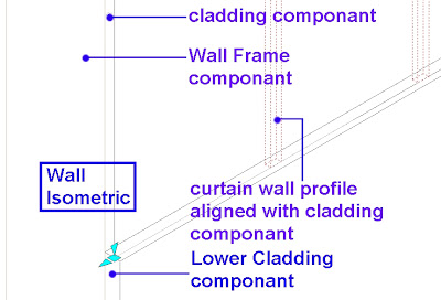 Now you can click on the wall and 'Restore' the body modifier but it won't restore a CWA but a MassElement in the shape of the CWA, so it would be easier to delete the body modifier and start again if you need to edit it, ie lengthen or raise the wall and the BodMod is too short. SO you need to keep the original CWA handy!


 Unfortunately there are other issues with the MR. I tried to render at 2200x900 and it crashed. (only 2GB of RAM). So I defaulted back to 06 though I will keep trying as well as upgrading memeory.
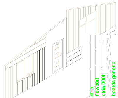
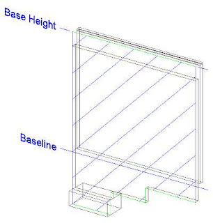
 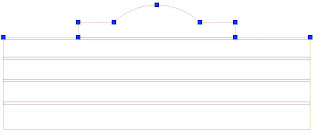 Select the wall and right click. Roof/Floorline - Edit Roofline option and now looking in your command line choose the 'Project to Polyline' option (P). Note: The red brick courses are defined as seperate componants in the wall style.
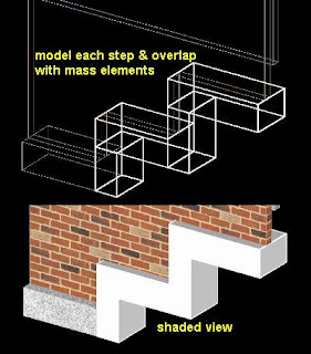
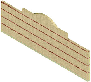 Now I need to add my top course header over the raised bwk and arch. Going back to the elevation view, I trace a pline over the top (not the wings), offset it 110, draw lines to join both ends and then select one PLINE, right click and select J (join). If you have trouble getting a closed PLINE, just trace over the whole lot using the arc option where required. This time the join option worked but it can be quicker to get the job done to just do it again. Now I tried to turn that closed PLine into a Mass Element but it would not even give me that option. Perhaps the USC wasn't correct. Regardless I just extruded it into a solid, then converted the solid into an ME.Now the final step is to add the ME as a Body Modifier to the wall. In this case I added it as an additive to the top course so it would use the same characteristics (red brick). Notice that it does not even touch this top course but it accepts the ME as an additive to it.
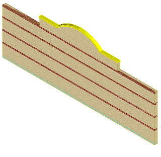

 Now that I have a handle on Body Modifier's, I find them indespensible. They cleverly & efficiently solve many of the little modelling issues you come across in building virtual models. But wait ... there's more!!


 Here you right click and add/remove vertices. It's a bit tricky but you can use polar & otracking to line things up quite easily. If you need to, draw a line in elevation before hand to snap your points to.
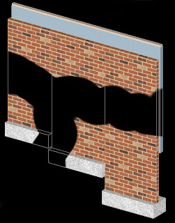


